I have stated some of my boards as “Arduino-compatible” as many other DIY and commercial electronics you can find nowadays. Simply put it means that you can develop Arduino programs (sketches) for that board with the Arduino IDE. Here are some information and references how to make a board Arduino compatible and what it means.
Use of the name Arduino
Arduino have done a lot of good for the maker community, bringing new people in and making it easier to approach electronics and embedded software. Not everyone may agree that all approaches Arduino use are optimal, especially when it comes to rather inefficient and high level code for tiny microcontrollers. However, Arduino have also brought loads of cheap hardware and unofficial Arduino-compatible products. And there is nothing wrong in creating Arduino-compatible boards – they even have a comprehensive list of unofficial microcontroller boards and shields on their website. There are still few things to consider if designing your own boards with Arduino in mind.
Arduino boards are released under the Creative Commons license and hardware is open source so you are free to use it and create your own modified designs. However, Arduino is a registered trademark and if you want to create an official Arduino product and use the name, you must talk with the core team. They do have a known and valuable brand and want to make sure that design, documentation, and manufacturing ethics are according to their standards. With an official Arduino product you also need to give something to the community to keep it running: licensing fee, design files, support, etc. See their guidelines on how to use the name Arduino.
While you must not use the name Arduino (or derivatives) in your own designs, you can describe the relation to the Arduino platform. This means you can call your device “yourname for Arduino” or “yourname (Arduino-compatible)”. Therefore, some boards I have designed are also Arduino-compatible. I have made that only to make it slightly easier for someone to use these boards and designs; after all, it is rather easy to make a microcontroller circuit Arduino-compatible.
Making a design Arduino-compatible
As a minimum your design must be Arduino-compatible by hardware and software. If you wish to share it with others, you should have some documentation as well.
Hardware
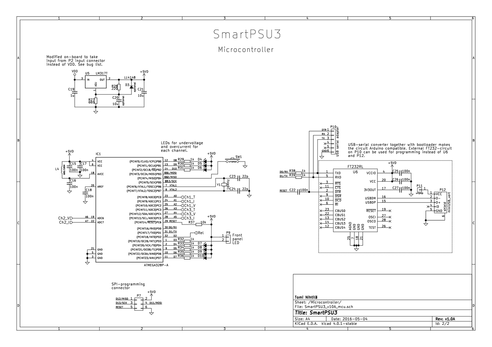
I have made my designs compatible with Arduino Nano, meaning using the same microcontroller and copying the programming interface. Below is schematics of microcontroller circuit of SmartPSU3.
 Important points here are (see photos below)
- Use of ATmega328P microcontroller (the same as on the Arduino board you mimic)
- TX/RX connection to USB-serial-converter; this serial IC (typically FT232) can be on-board or external
- Remember to cross-connect TX and RX between microcontroller and the serial IC
- R38 and R39 bring some protection in case pins are incorrectly configured
- C22 resets the microcontrolle via DTR signal
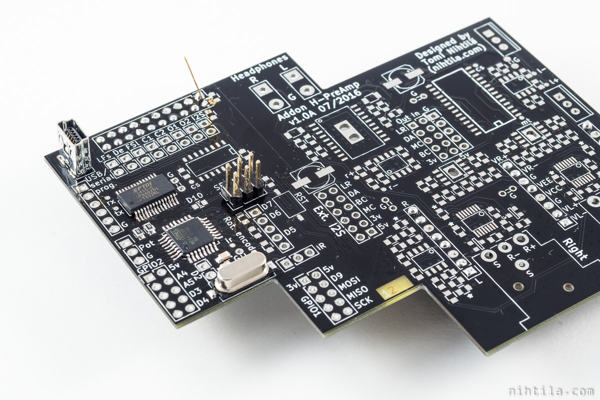
On-board FT232
In this case everything is populated on the application board and only USB-cable is required for programming (after bootloader is programmed). See example of Addon H-PreAmp board below. Note that you need to provide supply voltage when programming the bootloader if 5 V from USB is not connected to the board.
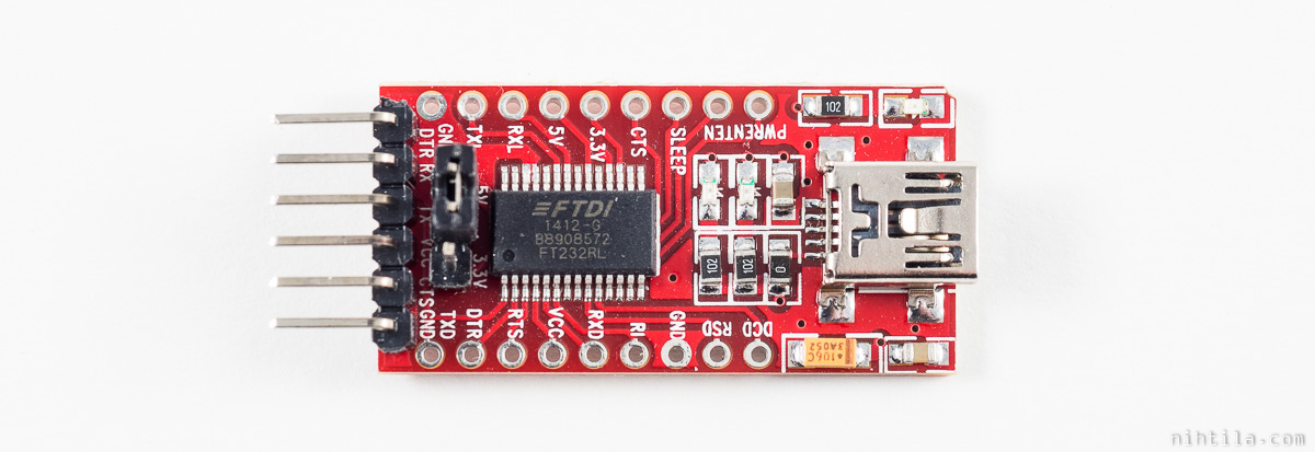
 External FT232 board
This option is available to save some money if using loads of Arduino-compatible boards. FT232 IC and USB connector cost money when purchased in single quantities. External FT232-boards can be purchased on eBay for very cheap prices.
I am using boards shown below.
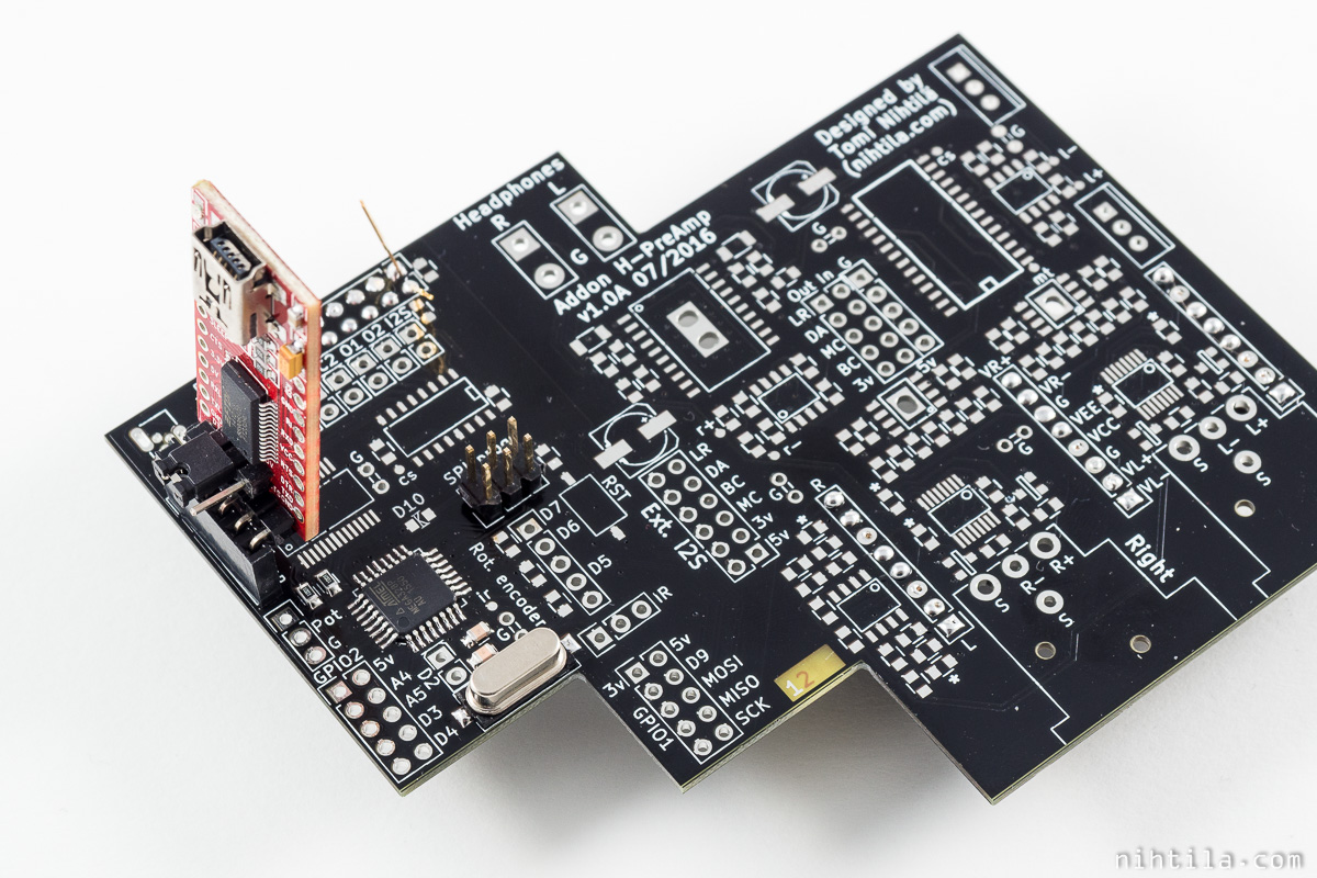
 When used on H-PreAmp board populated for external FT232-board, it looks like below. The board is not left there but only used when programming the device.
Software
First of all, there are two different programs in your functioning Arduino microcontroller: bootloader and Arduino sketch (your program). When you power up the device, bootloader starts and calls your sketch if it is loaded in the memory. Bootloader also programs your chip when sketch is uploaded from Arduino IDE. Empty microcontroller does not have anything running so the bootloader must be flashed by an external programmer. This is often done via SPI-interface. When the bootloader program is in place, it is possible to load Arduino sketches via Arduino IDE. This is done via UART serial interface. The difference is that now the bootloader reads the program from UART and programs another part of the microcontroller (still preserving itself in the bootloader section of the memory), so called self-programming. Then you technically have two softwares in the microcontroller: the bootloader and the actual software. Bootloader just hands the execution over to the actual software unless new sketch is uploaded.
Bootloader must be programmed before the microcontroller is recognised by the Arduino IDE. To do that, following minimum hardware must be used:
- Populate microcontroller and necessary components for it to function:
- Decoupling capacitors
- Crystal oscillator and its capacitors
- Oscillator frequency depends on the Arduino board you want to mimic; typical value for many boards is 16 MHz
- Programming connector
- SPI programming is used here
- Provide supply voltage for the circuit
Load Arduino bootloader to the microcontroller
These instructions are applicable if you have soldered the parts yourself or know you have unprogrammed microcontroller. If you have a fully populated Arduino-compatible board, someone else has likely done this for you already.
As you have an empty Atmel microcontroller, you need to program the bootloader software before it is possible to program the microcontroller with Arduino IDE. To burn the bootloader, you need an external Atmel AVR programmer or you can do it with another Arduino board.
- To burn the bootloader with another Arduino board, check instructions here https://www.arduino.cc/en/Tutorial/ArduinoToBreadboard. You will need to wire the Arduino board to the SPI-connector of the application board. In nihtila.com boards the microcontrollers are SMD-packaged so they cannot be detached. Therefore, you need to power up the application board when programming. Do not connect VCC from Arduino board (but do connect GND). Check that supply voltages are the same (5 V).
- To burn with an external AVR programmer supported by the Arduino IDE, see instructions here https://www.arduino.cc/en/Main/Standalone.
- If you have an external AVR programmer that is not supported by the Arduino IDE, the instructions above do not work. Then the only option is to manually program the .hex file and set fuses. I have burned bootloaders with AVR Dragon using Atmel Studio, following the instructions here http://forum.arduino.cc/index.php?topic=125622.0. Bootloaders can be found in C:\Program Files (x86)\Arduino\hardware\arduino\avr\bootloaders (if you installed Arduino IDE in the default location).
- If you are interested in buying one of my boards that is Arduino-compatible but do not have the hardware mentioned here or do not understand what to do, you can ask me to program the bootloader.
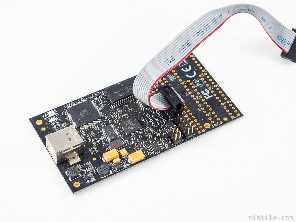
AVR Dragon I use is shown below. It is a cheaper end official Atmel programmer but still costs too much (around £50) for many hobbyists for occasional use. I have it because it supports JTAG-based in-circuit debugging I like to use in non-Arduino projects with bigger microcontrollers).
Use without Arduino
“Arduino” is just one way of using and programming microcontrollers. It has a big community in the background and wide support, loads of libraries, etc. Makers who have been doing embedded code before Arduino, like myself, probably prefer using pure C with Atmel Studio or other development environment. I also encourage going beyond Arduino if you are more interested in embedded programming.