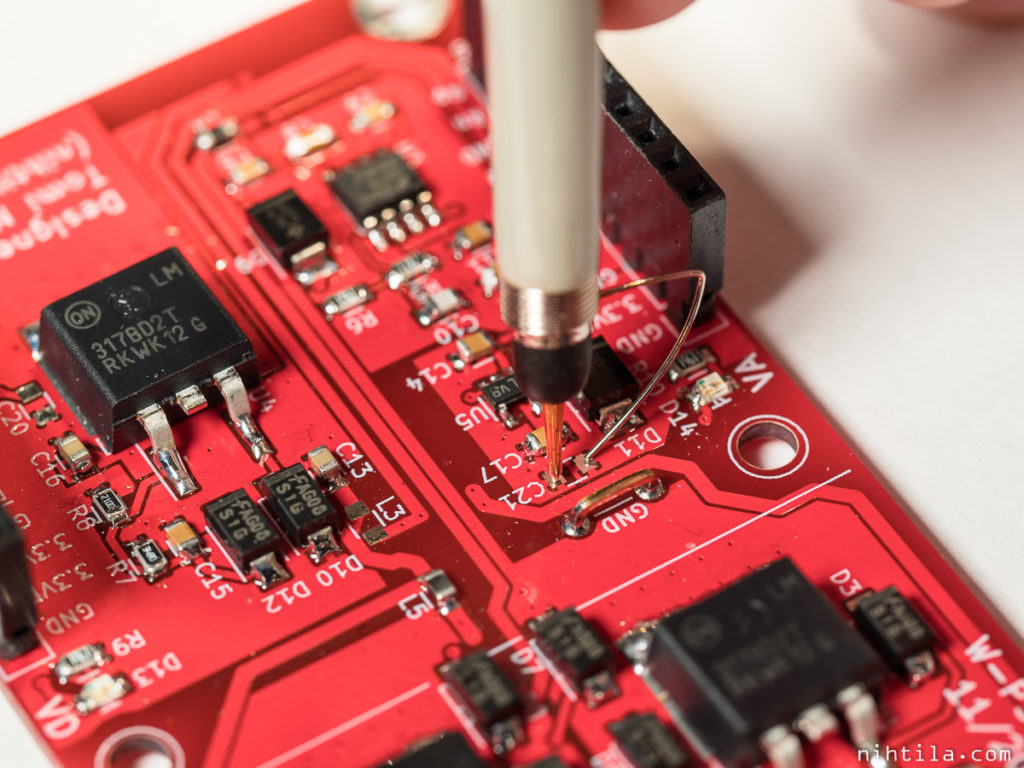
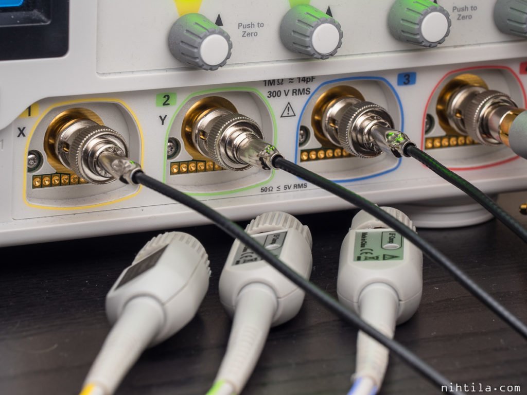
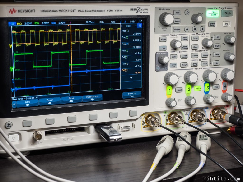
These DIY probes are great addition to oscilloscope or other measurement instrument due to:
- Easy to build
- Low cost
- High bandwidth
- Robust
- Can be equipped with suitable connector or soldered directly on circuit under test
Introduction
Before presenting this great tip I must admit I did not come up with this idea. This type of measurement probe is presented in the book High Speed Digital Design – A Handbook of Black Magic by Howard W. Johnson and Martin Graham. I first saw the idea written by fellow DIYer Janne Ahonen but he also gives credit to Howard Johnson. Please refer to Janne’s article for more technical explanation of the probe, followed by measurements.
Here are instructions how to build and use these probes along with plenty of photos. There are no measurements done to present for now.
Problem of conventional probe
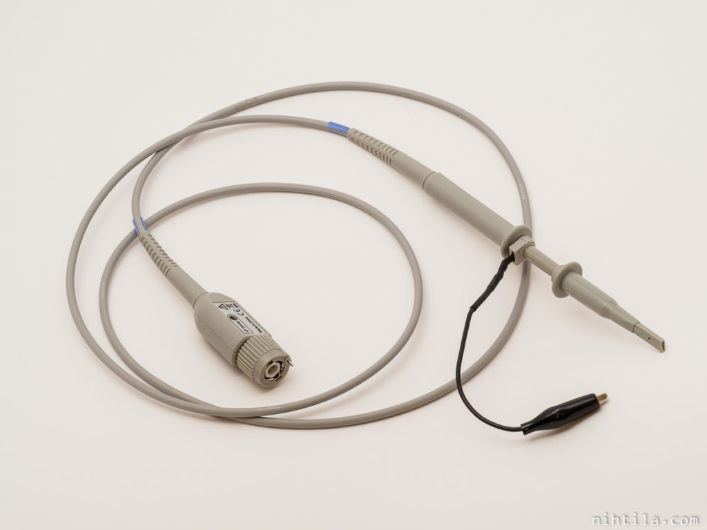
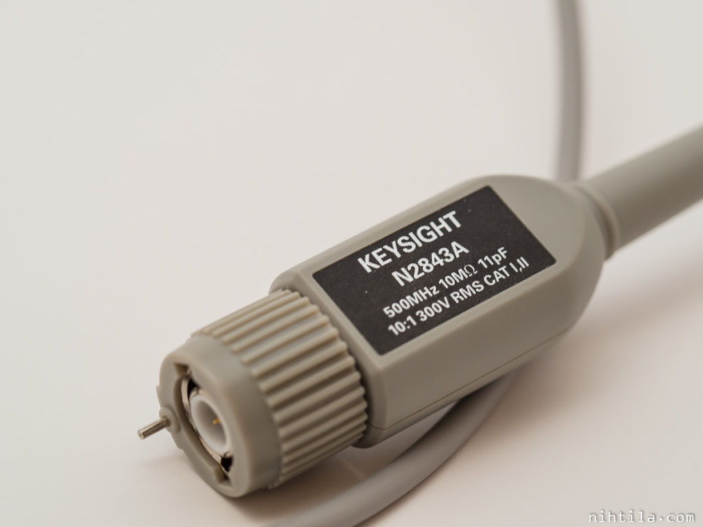
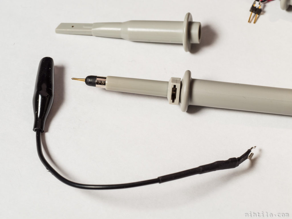
Conventional oscilloscope probes are ok for basic measurements but have several limitations. A practical one is that they may be clumsy to use with big plastic case and a clip that does not stay anywhere. The probes of my relatively expensive Keysight scope are good example; in fact they are among the worst ones I have used. Traditional scope probes are a bit of a remnant from the past. If you want to buy an active high-bandwidth probe from your scope manufacturer, prepare to pay 1000+ dollars even for the ‘low-bandwidth’ models (that is maybe 1 GHz).
Another limitation is bandwidth. Many hobbyists may not be concerned about that as it becomes significant when going beyond 300 MHz or so, usually higher than hobbyists’ scope bandwidths. Bandwidth is mainly limited by the probe capacitance.
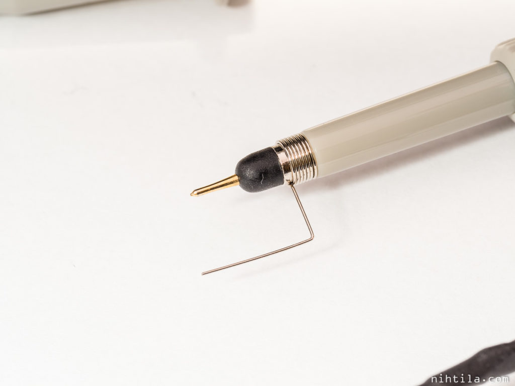
However, in order to get even close to the bandwidth of even a conventional passive probe, one must not use the alligator ground clip. This creates a huge ground loop with significant inductance. If you want to measure higher bandwidth signals, the provided barrel spring connector must be used. However, that thing is incredible cumbersome to use!
DIY probe
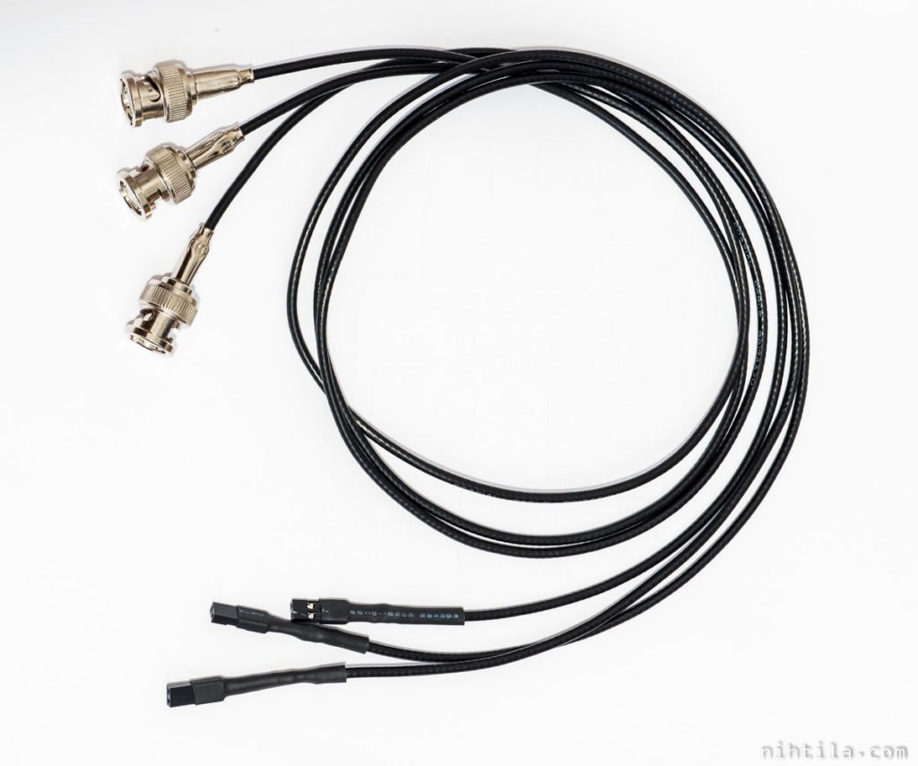
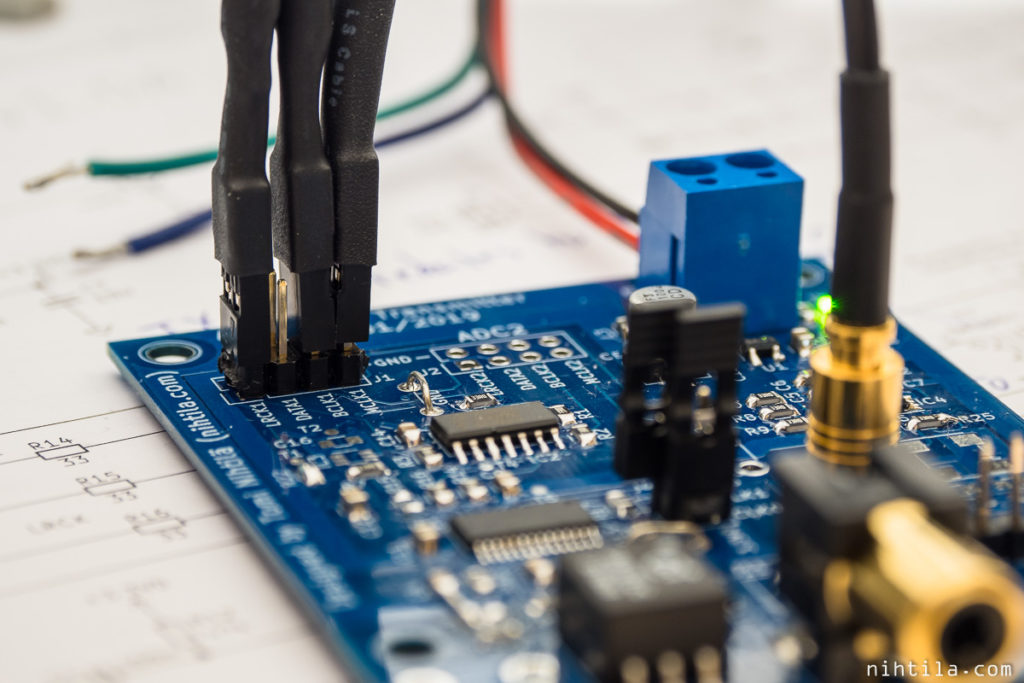
Using just a BNC connector, coaxial cable, and a resistor one can build a robust DIY probe. In addition, preferred connector can be soldered at the end, or the probe can be soldered directly on the circuit under test for optimal connection, as Howard Johnson used in his book. This really makes these versatile. Just make enough of them! I used 2.54 mm female pinheaders as this is the connector I often use on my boards.
Besides the connectors and cable, there is a resistor at the end of the probe – as there is in a conventional scope probe as well. This resistor (and parasitic capacitance) along with the scope input impedance determines the overall loading impedance to the circuit, and the ratio of these impedances is the attenuation ratio. Conventional probes have total 10 MΩ impedance; 1 MΩ in the scope + 9 MΩ in the probe giving the familiar 1:10 attenuation.
RG-174 is a nice coaxial cable to use because it is thin and flexible. Howard Johnson and Janne used 1kΩ resistor to achieve 21:1 attenuation ratio when terminated at 50Ω. I used 953Ω to get (near) 20:1 ratio that can be selected in some scopes.
Impedance and attenuation
The target impedance here is not 10 MΩ as it is impossible to keep such high impedance at high frequencies, capacitance effectively being the bandwidth-limiting factor. Instead it is 10 000 times lower – 1 kΩ. While this will not be a problem in most circuits, it is one limitation of this probe and a price to pay for high bandwidth. Only active probes can have both high bandwidth and impedance (and price!).
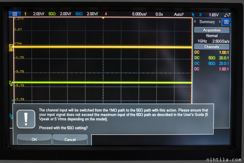
To cope with the low impedance, the receiving end at the oscilloscope must be 50 Ω terminated. Many oscilloscopes have internal 50 Ω termination that can be selected instead of high-impedance 1 MΩ input. If not, inline terminator similar to this must be used.
Building a probe
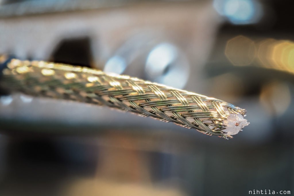
I used RG-174 coaxial as it is thin and flexible.
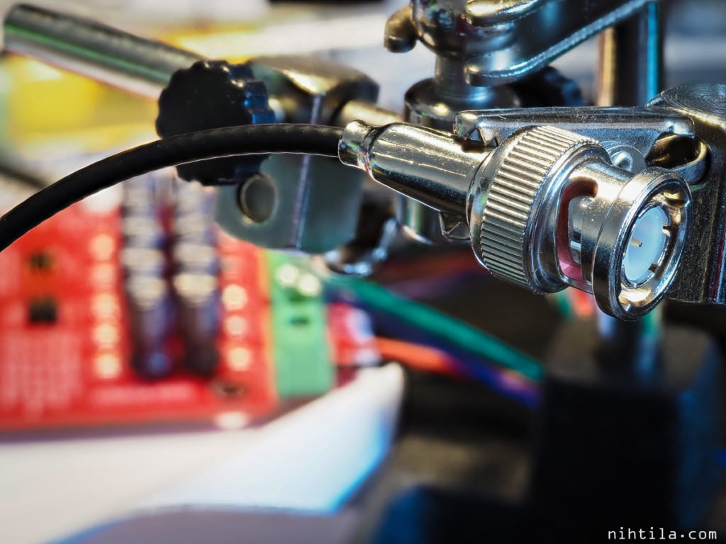
I do not have BNC crimping tool so I used normal pliers. If aiming for really high bandwidth, this may have an impact. However, in that case you need to characterise the probe anyway.
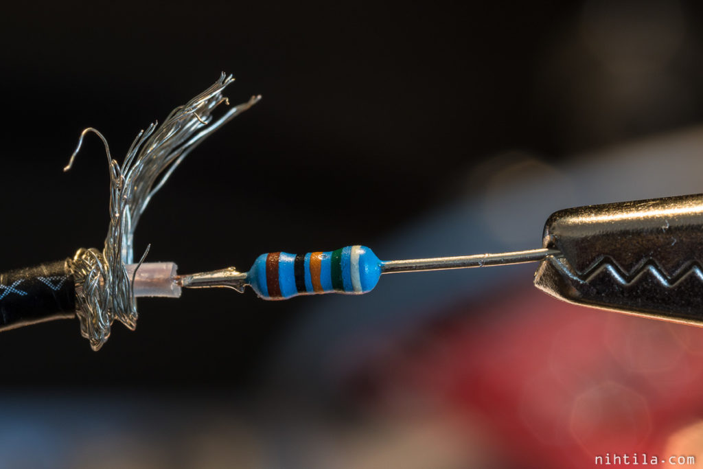
Next I soldered the resistor at the end of the cable. I haven’t used through-hole resistors in ages!
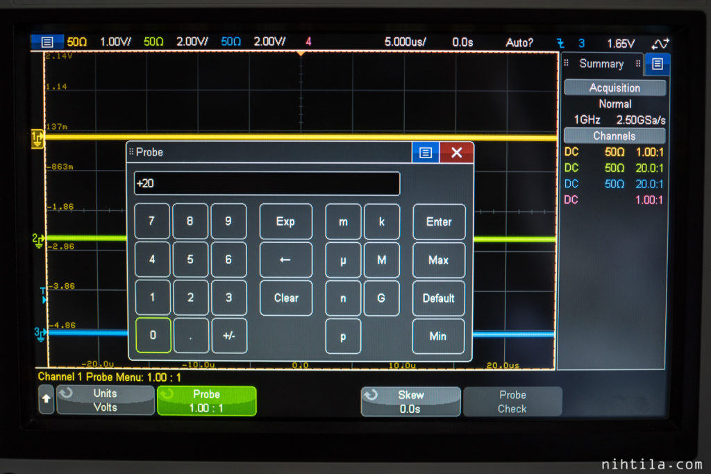
This is a 953 Ω resistor that together with the 50 Ω scope impedance will give (roughly) 1 kΩ total impedance and 1:20 attenuation. I chose this as some scopes, such as older Keysight 3000 series, only have fixed ratios to choose from and 1:20 is one of them.
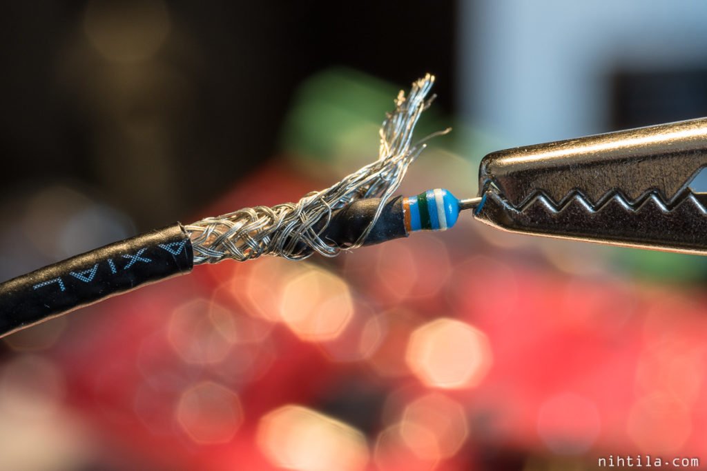
I added small heat shrink around the resistor so that I can partly cover it with the coaxial braid.
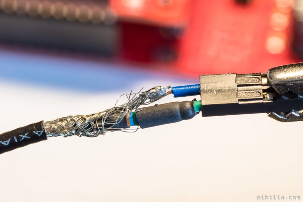
And then soldered the pinheader
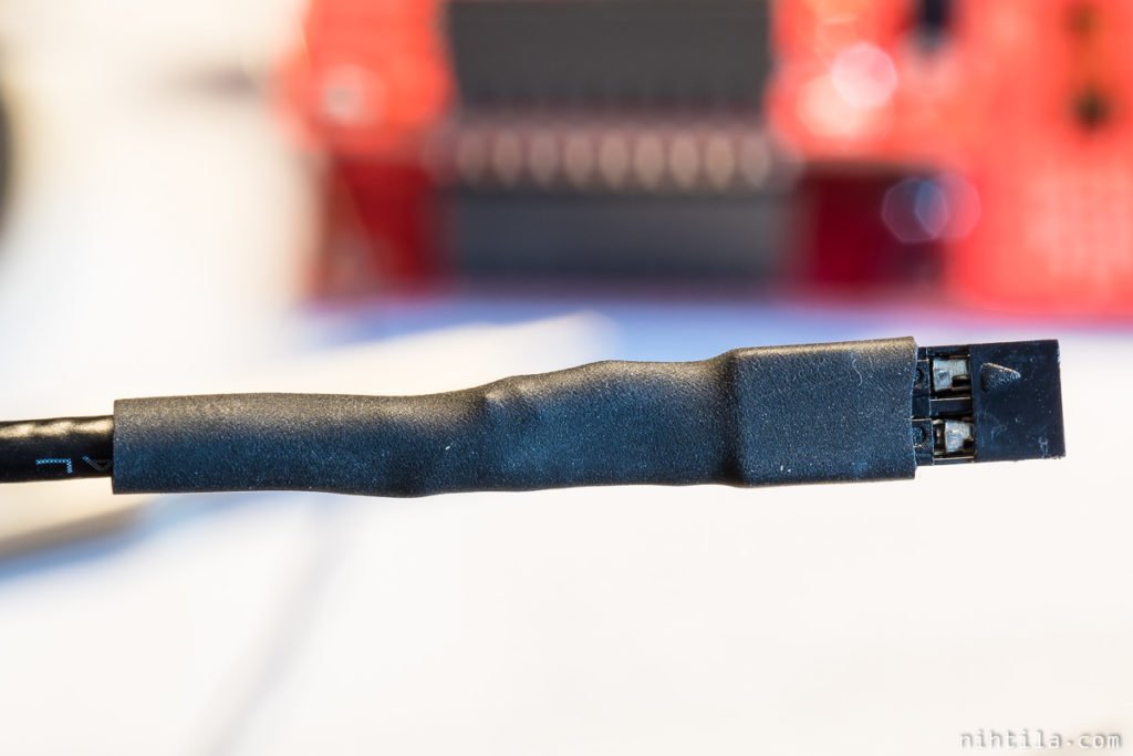
and finished with heat shrink.
I made three probes for now but will make a couple more.
Using the probes
When using these probes, oscilloscope clearly cannot recognise what is plugged in like with the stock probes.
First of all, the oscilloscope input must be set to 50 Ω, or use inline terminator.
Then the attenuation ratio must be chosen correctly in order to read correct voltages. As mentioned above, some scopes have 1:20 ratio as the closest so 953 Ω resistor is a good choice in the probe. However, if your scope lets choose the ratio freely as my 3000T you can pick 1 kΩ resistors and choose 1:21 attenuation.
I have used 2.54 mm / 0.1″ female sockets in these as I use pinheaders a lot in my boards.
Performance and conclusions
I claim this to be a high-bandwidth probe but I would need to measure it to be sure. I can only assume the bandwidth is higher than in a conventional scope probe – but how high I do not know. I will try to measure it one day with appropriate measurement kit. Janne’s article gives an idea what it can be but small things can cause large variations towards the end of the useful bandwidth.
Nevertheless, the practical improvement in usability is already good enough motivation to build a bunch of these probes. I have been using them quite a lot already.
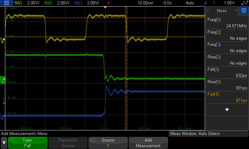
These edges have around 500 MHz bandwidth but I suspect there is still plenty of headroom in these probes
References and additional information
- Johnson, H. W., Graham, M., High-Speed Digital Design, A Handbook of Black Magic, Prentice Hall, 1993.
- Janne Ahonen: A wideband 1:21 DIY 1 kΩ oscilloscope probe
Edit 14/04/2019: I made a brief video about the probes:

