
- LM4562 and NE5532 show almost identical performance in I/V stage, while OPA2134 is 2 dB weaker.
- LM4562 is the best performer in differential amplifier.
- The best solution is to use NE5532 in I/V-stage and LM4562 in differential amplifier as it gives almost identical performance to all-LM4562 implementation
- Differences in distortion are mostly due to odd left/right channel differences of PCM1794A.
Introduction
PCM1794A has differential current outputs and therefore requires some analog circuitry. Most of the circuits, including the TI reference design in the datasheet, use operational amplifiers as it is the easiest approach to excellent performance. The current output has 7.8 mApp swing with -6.2 mA common mode level. Therefore, circuitry is required to convert current into voltage, remove the common mode signal, perform some low-pass filtering, and in many cases convert the differential signal into single-ended.
These measurements have been performed on H-DAC boards, analog stage schematics can be seen below. Three opamps have been measured:
- NE5532; very old and widely used workhorse in consumer and professional audio equipment, mostly due to its excellent price/performance ratio
- OPA2134; quite popular TI JFET opamp that I have used in my older designs – before I had access to measurement equipment
- LM4562; ex-National now-TI part, considered as one of the best and still affordable opamp – it is also the most expensive of these
Three H-DAC boards in these measurements are named A, B, and C: A board is all NE5532, B is LM4562, and C is OPA2134.
Measurements were performed with APx585 audio analyser connected directly to the I2S input of PCM1794A.
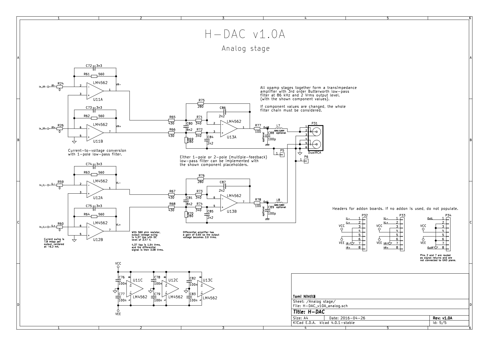
H-DAC output stage schematics.
I/V-stage
I/V-stage (U11 and U12 circuits) is transimpedance amplifier, changing the current output of PCM1794A into voltage. Opamp acts as a buffer and impedance converter but effectively only the shunt resistor (R61-R64) determines the output voltage by simple Ohm’s law U=I*R. Therefore, with default resistors of 560 ohm the output swing is 4.37 Vpp (1.54 Vrms) with 3.47 V DC level (common mode voltage). If resistor value is changed, it changes the gain of this stage, affecting these voltages and also noise and distortion level.
Analog signal is measured with APx585 after I/V-stage with the presence of the common mode signal.
Shunt resistor
I have made THD+N vs. amplitude measurements (below) with 1 kohm and 280 ohm resistors, meaning roughly +5 dB and -6 dB gain compared to the default 560 ohm, respectively. These are seen below: solid lines are 560 ohm and dotted 280 ohm (green) and 1 kohm (red).
Going from 560 ohm to 1 kohm, noise floor increases 4 dB and full level distortion figures 4-5 dB so there would be little or no improvement in SNR and THD+N as signal level is increased by 5 dB. With 280 ohm, noise floor is 3 dB lower and full level distortion 5-6 dB lower.
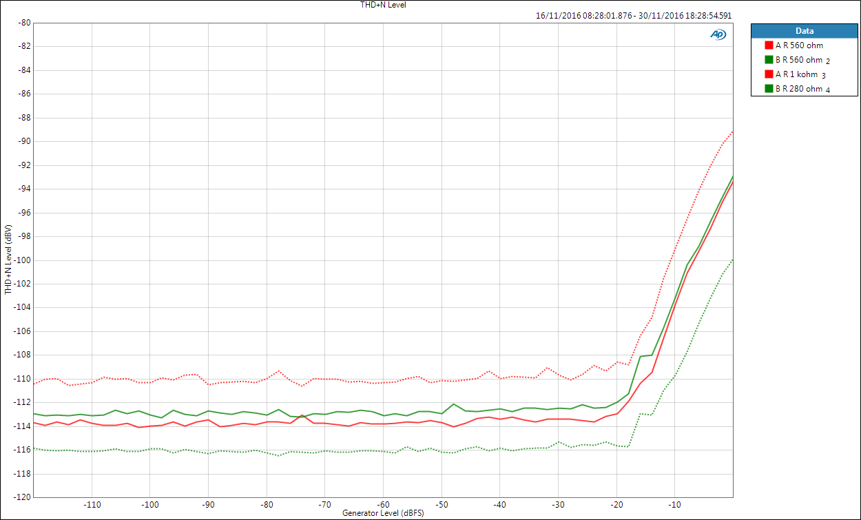
I/V-stage shunt resistor comparison.
Opamp
Below are THD+N vs. amplitude for all opamps (with 560 ohm shunt resistors). Noise level is basically the same in LM4562 and NE5532, while OPA2134 is 2 dB weaker. THD+N level of all right channels is almost identical at -94 dBV. Left channel is 5-10 dB better but there is also more variance between boards/opamps.
Notice that in shunt resistor measurements above noise level of NE5532 (A board) is approximately 1 dB better than LM4562 (B board). There must be some differences between parts as well.
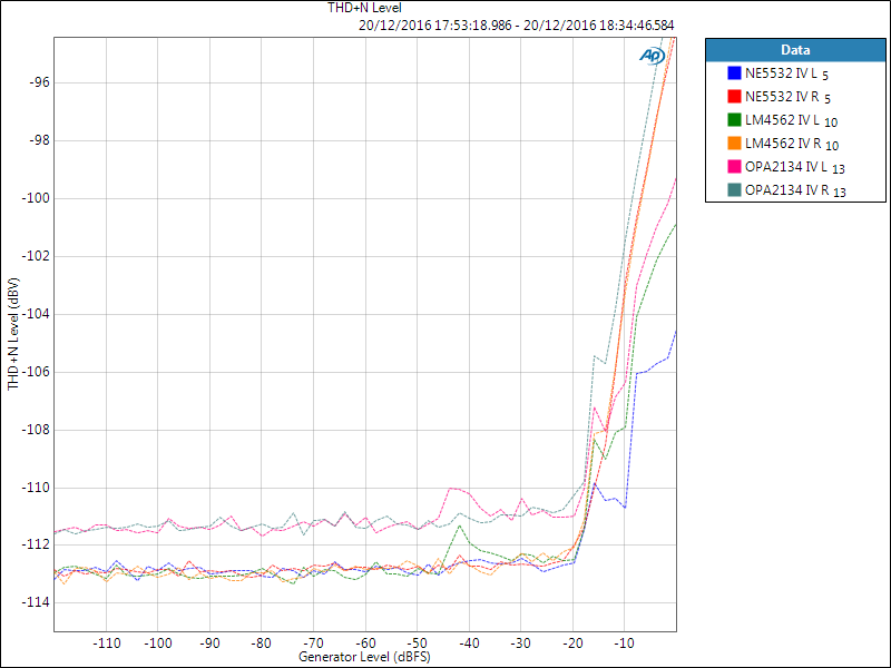
I/V-stage opamp comparison.
Single-ended output performance
While measurements above were taken in the middle of the circuit, this is measured at RCA outputs, after I/V-stage and differential amplifier. Differential amplifier stage has a gain of 0.65 (-3.7 dB).
Clear difference in noise level can be seen between opamps: LM4562 is the winner, then NE5532, and OPA2134. When comparing to the plot above, it is interesting to notice that LM4562 has improved, while the other two have got slightly worse. As differential amplifier stage attenuates, we could expect more improvements. One could also try to decrease the gain at I/V-stage and keep differential amplifier gain at 0 dB.
In distortion figures things are not as consistent. Again right channel seems to be weaker.

Opamp comparison after differential amplifier.
Based on the results seen, next one is interesting: NE5532 in the I/V-stage but LM4562 in the differential amplifier. I tried this because of the results seen above – both opamps have almost identical noise performance at the I/V-stage but LM4562 takes the victory at the differential amplifier. It can be seen that performance is almost the same as LM4562-only – therefore this is definitely the most cost-effective choice between the tested opamps. It does not really come as a surprise that NE5532 performs so well in the I/V-stage as it is also used in the TI reference design.
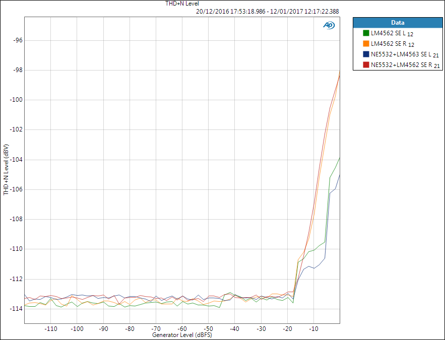
Overall output stage opamp comparison.
Conclusion
There are some differences in noise level between the measured opamps and killer combination from these tests is NE5532 in the I/V-stage and LM4562 in the differential amplifier. Differences in distortion are more difficult to quantify as there are oddly some big differences between left and right channel. I have addressed some of these issues in another post.
Higher SNR can be achieved by setting higher gain but this has meaning mostly from marketing point of view as signal level of few volts can rarely be used. Consumer electronics have maximum input level in the range of 0.7-2 Vrms and the best practical SNR can be achieved when gain matches the listening levels.
I did not try to look for the optimal noise solution by swapping the gain between I/V-stage and differential amplifier.
While it is interesting to look for the best solutions, it is also good to recall that we are dealing with noise levels of few micro-volts. Small variations unlikely have any practical meaning.