
HP Buf headphone amplifier’s already excellent THD+N figures can be pushed extremely low by replacing OPA2134s with LM4562s. This gives huge performance boost:
- 5-8 dB lower noise floor, depending on gain setting
- Up to 12 dB better THD+N
- For example, THD+N at 100 mW into 32 Ω went down from 0.00065 % (-104 dB) to 0.00017 % (-115 dB)
See original HP Buf post for more detailed information. There I have mentioned that it looked like opamp was the performance-limiting factor of the circuit. I used OPA2134s as I had them laying around. Furthermore, FET-input-opamp sounded like a good idea due to very large common-mode input resistor.
Below is the updated schematic, denoted as revision B. Compared to original, opamp model was changed from OPA2134 to LM4562. Also 100 uF electrolytics have been populated but these had no impact on performance in these measurements. PCB is the same.
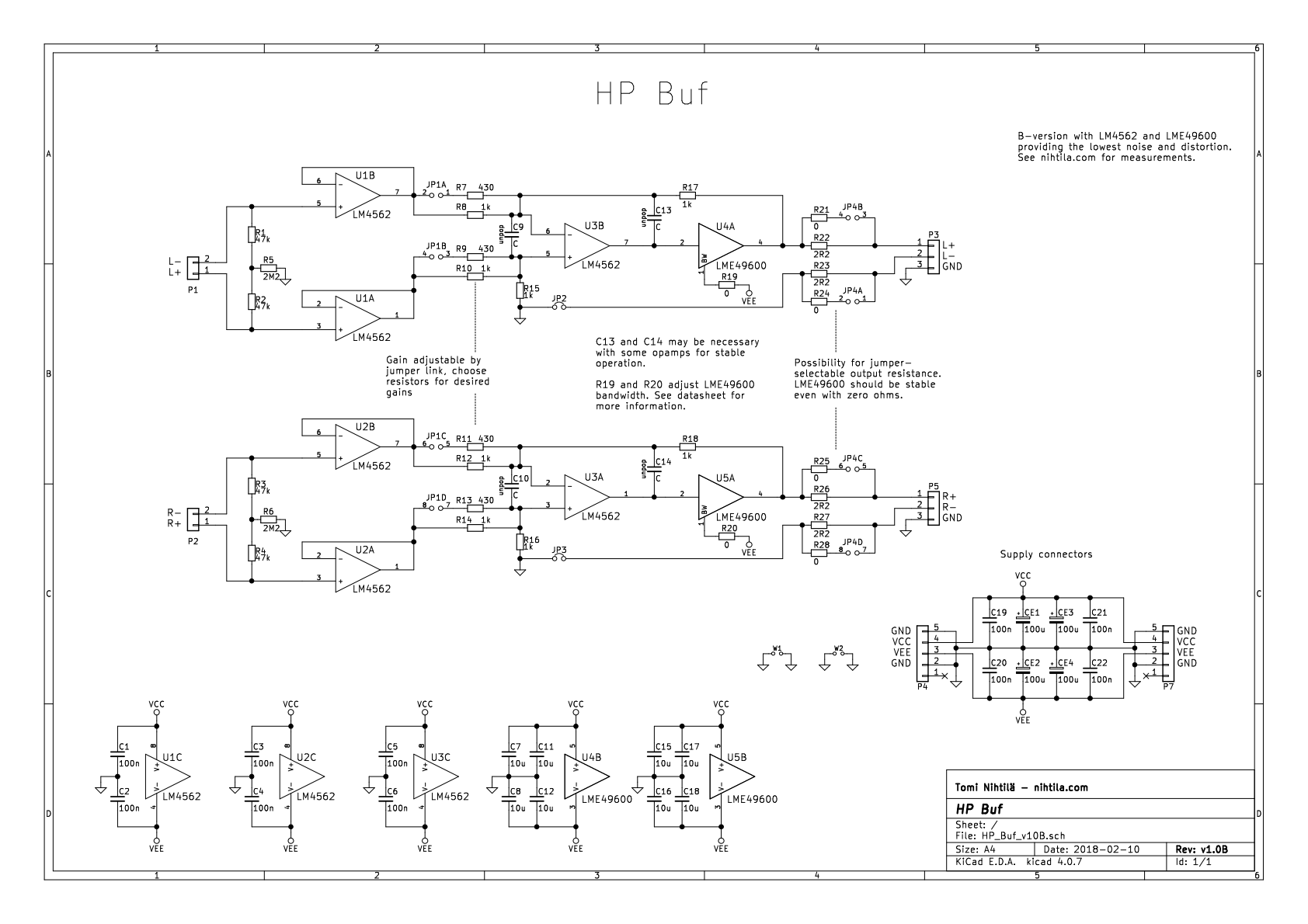
Design considerations
There are two considerations when changing opamp model in this circuit. First, if opamp input bias current is very high, it can generate significant DC offset due to 2.2 MΩ common-mode resistor. However, common-mode DC does not show up at the output due to differential amplifier. But if there is large difference in opamp input bias currents – large input offset current – this can create DC voltage that in turn shows up at the output. However, this current is affected by the 47 kΩ resistors so it is likely to be barely measurable.
With BJT-input LM4562, I see 8 mV and 25 mV common-mode DC in my board. Differential DC is negligible and all four outputs show 0 mV DC. When looking at LM4562 datasheet, it is also clear DC is not a problem. While maximum values can be significantly larger, typical input bias current is 10 nA and input offset current 11 nA. 10 nA means 22 mV in 2.2 MΩ but less than a millivolt in 47 kΩ.
Second aspect is stability of the amplifier loop. In some cases capacitor C13/C14 must be populated in order to maintain stability. LME49600 datasheet gives some examples of this.
Performance measurements and comparison
I have measured the board at work using Audio Precision APx555 audio analyser. Unless otherwise mentioned, measurement bandwidth is 20 kHz and frequency in single-tone measurements is 1 kHz. In fact, I needed to re-measure these as at first I did not have “high performance sine analyzer” selected in APx555. This low distortion levels require seriously good analyser.
The board is powered by a bench PSU and loads are resistive using a headphone load box.
Measurements were performed using balanced outputs on HP MoBo. Unbalanced output would lead to poor crosstalk.
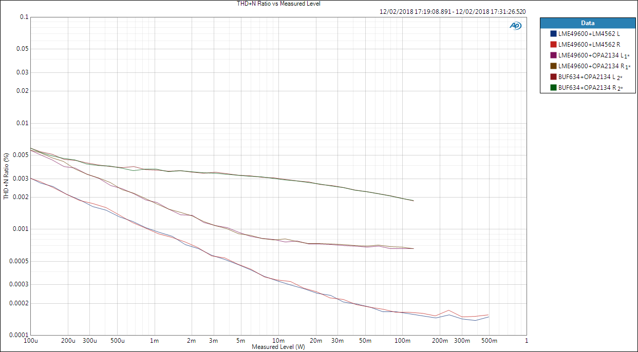
THD+N comparison into 32 Ω
Below are THD+N ratio vs. output power sweeps into 32 Ω load, with low (0 dB) and high (10 dB) gain settings. Highest curves are OPA2134+BUF634, middle LME49600+OPA2134 and lowest LME49600+LM4562.
With LM4562 sweep goes until 4 Vrms input level, while before it has been up to 2 Vrms, that is why the lowest curves goes all the way to 500 mW. I just wanted to see if distortion remains low if higher input signal level is used. And it does. These are extremely low levels of distortion.
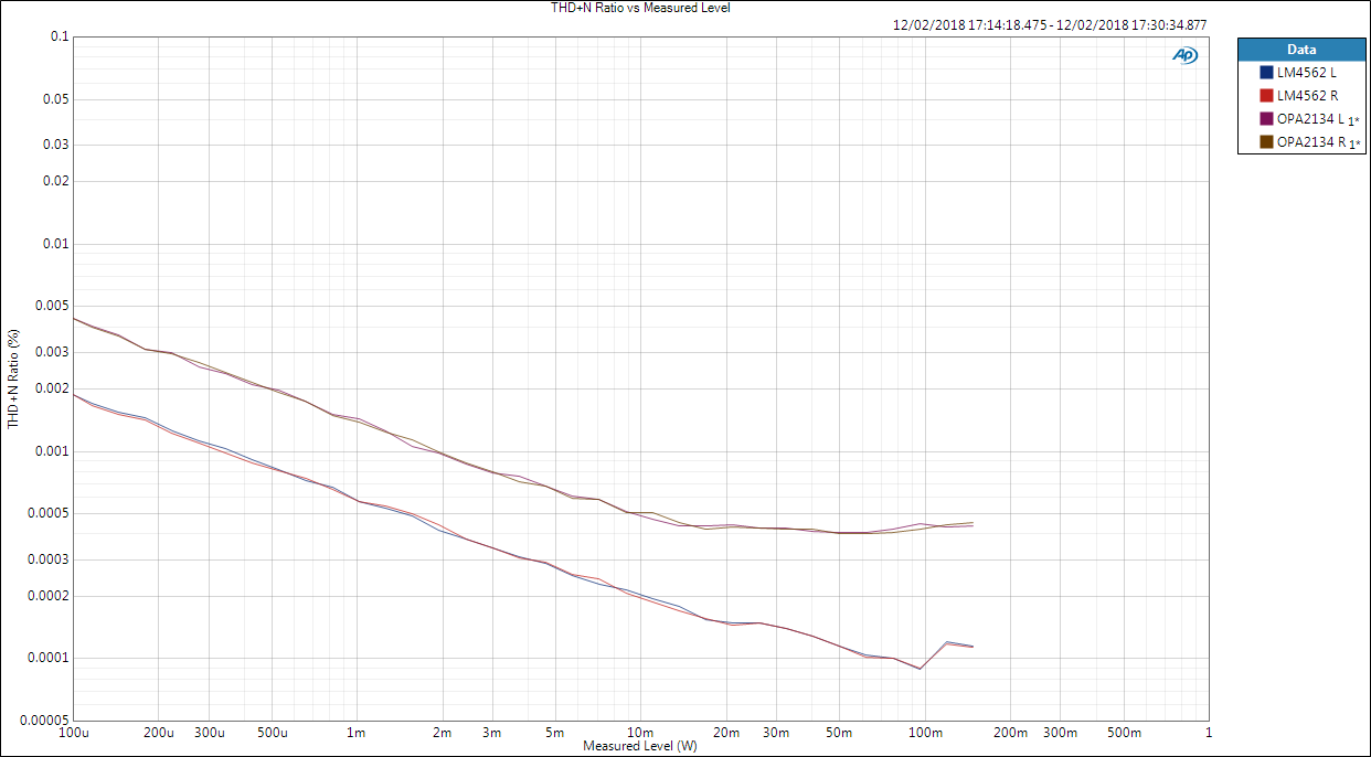
0 dB gain, 32 Ω, comparison
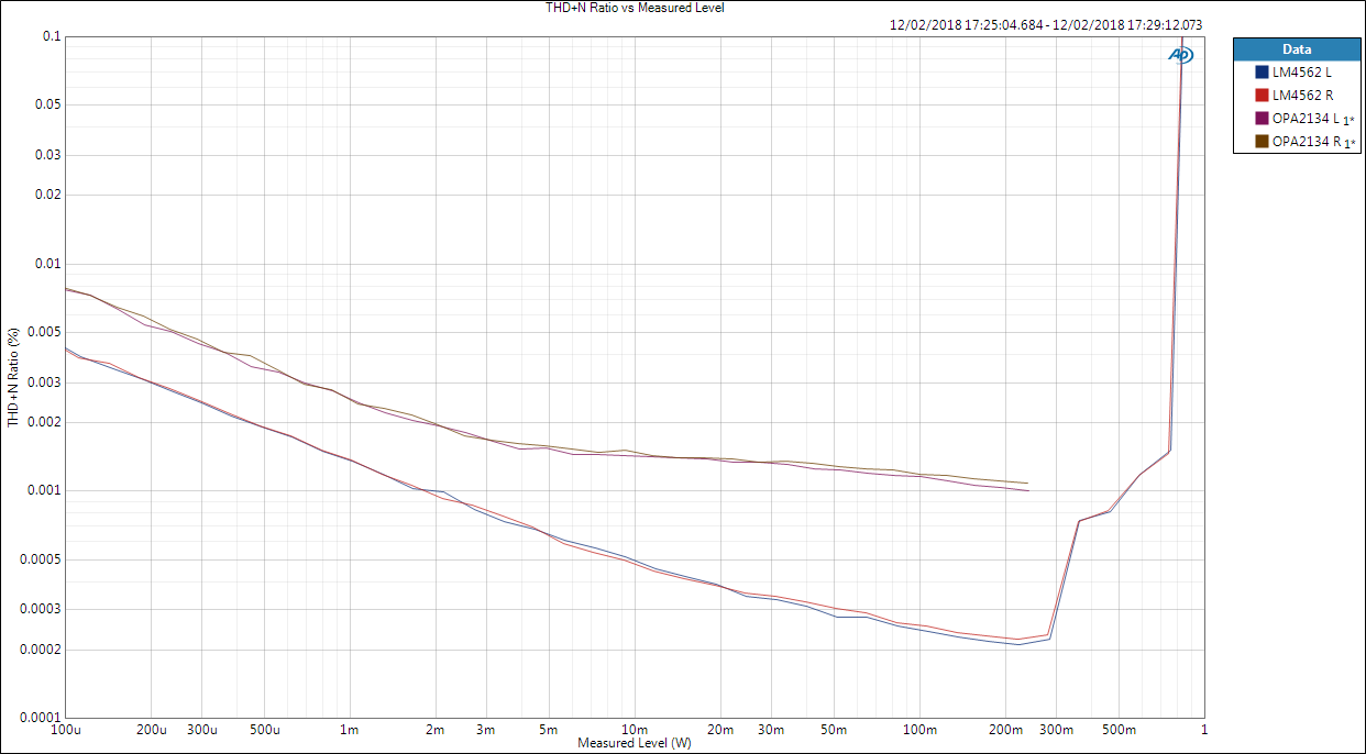
With higher gain the output power capability is reached.

10 dB gain, 32 Ω, comparison
THD+N into 300 Ω and 16 Ω
LME49600 and comparison between OPA2134 and LM4562.
High gain, 300 Ω:
10 dB gain, 300 Ω, OPA2134 vs. LM4562 (LME49600 buffer)
High gain, 16 Ω:

10 dB gain, 16 Ω, OPA2134 vs. LM4562 (LME49600 buffer)
Low gain, 16 Ω:
0 dB gain, 16 Ω, OPA2134 vs. LM4562 (LME49600 buffer)
Noise floor and SNR
Noise floor (non-weighted):
- 0 dB gain: -115 dBV
- 10 dB gain: -110 dBV
Noise floor kind of tells more than SNR as the latter depends on the used reference level. But for example, if we used 4 Vrms (12 dB) level as in above 32 Ω graphs, SNR would be 127 dB. Add A-weighting and we’re approaching magical 130 dB limit. 4 Vrms is obviously already very high signal level.
Conclusion
Here the opamp swap really does make huge difference in measurement results. Next question is can we get even better? LME49600 datasheet states so high numbers that there are room for even more improvement. For example, TIs relatively new OPA1612 opamp throws in even better performance figures than LM4562. Maybe I will need to add few of those in my next component order…
While it might be of technical interest to push the figures even lower, great practical question is where do we get good enough signal for such clean amp? If you don’t want to listen to only sine waves from Audio Precision, that is one longer-term challenge in the DAC domain.
References and additional information
Version history
This page version history
- 21.2.2018 Initial version
4 comments
Hi!
You wrote the LM49600 is stable even with 0 Ohm output resistor. Is it true? I fear I get problems with capacitive loads (>1nF). Do you have expierience with it?
best regards
R.
I don’t have experience. It’s possible to lose stability at some point but the datasheet shows no series resistors. It is something I have been thinking about checking one day but have not done so yet.
Hello,
you write that it is possible to operate with 0 Ohm output resistor,
I have two questions about this case:
1.)
in this case the mute circuit (relay) on HP-MoBo makes a hard shortcut to ground at the output of the LM49600,
is that “allowed” / not harmful to the LM49600 ?
2.)
how is the concept of impedance balance (‘pseudo balanced’ output) maintained in this case ?
like described here (http://nihtila.com/2018/08/06/benefits-of-balanced-headphones-interconnection/)
especially this picture http://nihtila.com/wp-content/uploads/2018/08/hp_xtalk3_2.png
in this pic: the orange 1 Ohm resistors (in the cold signal) are zero then and the black 1 Ohm resistor can be seen as the LM49600’s output impedance (?)
to be a nitpicker: in this case would it be better to make the orange resistors (in the cold signal) equal to the LM49600’s output impedance ?
or is this so very low that it doesn’t matter ?
Yes I use 0R. I have jumper to choose between 0R and 10R but imo 0R sounds better.
1)
It’s maybe not something you’d do in a commercial device but I haven’t seen any harm after using it for quite a while. After all, the output is almost zero (if not playing music), secondly the short is only on for a second or two. Furthermore, these ICs are short-circuit and thermally protected.
2)
Your thinking is correct. Impedance balance is not perfect; although it rarely is. But in terms of impedance balance, adding series resistor would be beneficial as now there is almost no resistance in the path, giving capacitance more significant impact on overall impedance. Buffer output impedance is very small (too small to compensate with resistor) as it is inside the feedback loop and pushed down by loop gain.
.
Further note: I am actually using this amp with normal 6.3mm unbalanced connection now simply because it sounds better. I presume this has something to do with my balanced cables though, they are very clumsy and bad connections. These Hifimans have 2.5mm plugs which are tricky to use as there is so little space that almost no connector fits there. I should try to find suitable connectors and build new cables. I would also advise using 4-pin XLR (which is more common in balanced HPAs) instead of 2x 3-pin which is too clumsy due to two thick separate cables. I will make this change in my amp (mostly just new panel) when I make new cables.
Comments are closed.