
- In balanced connection both speakers are individually connected to amplifier using two wires for each channel
- Crosstalk can be improved by tens of dB by using balanced interconnection
- Common-impedance coupling seriously limits crosstalk in conventional unbalanced headphones
- Balanced output can be easily and cost-effectively added on designs; inverted signal is not required
Here is a brief introduction to balanced interconnection and its benefits. The main focus is on the reduced common-impedance coupling which is more significant benefit in balanced headphones than noise suppression which is often considered the main reason for going balanced. Crosstalk measurements are also provided comparing unbalanced and balanced connection.
Line-level balanced interconnections are not discussed here in detail but as it is a well documented topic, references are provided.
Balanced vs. unbalanced headphones interconnection
Balanced interconnection is a common concept in electronics and used in numerous applications from very sensitive analog signals to high-speed digital buses. Balanced interconnection always means two conductors are involved in signal transfer but there is often confusion and misinformation regarding the meaning of balance.
Impedance balance
The most important thing to understand is that the word balanced in interconnection refers to impedance balance; the two signal conductors have equal impedance to ground (or some other reference). It does not mean that two signals of opposite phase are driven although this is often the case and can have additional benefits. However, the main advantages come from the impedance balance between the two conductors.
Regarding balance, the whole chain of output, cable, and input are of interest. Moreover, inductance and capacitance must be taken into account as well, not only resistance.
Although my wording is not exact and perfectly consistent either, I would like to say that a system or interconnection is balanced, not signal. Signal is differential, as is the following input stage.
Unbalanced (single-ended) example
Below is an illustration of a conventional single-ended connection to a headphone speaker; in a line-level example there could be an input stage instead of a speaker. Let us assume the amplifier has 0 Ω output impedance and the 1 Ω resistor represents the output impedance. Return path is ground-referenced and in practice the shield in the cable (if there is one) acts as a shield and return signal path.
This is a conventional single-ended connection and it is unbalanced as the hot lead has 1 Ω impedance to ground but the cold lead has 0 Ω impedance to ground. In practice there are of course impedances in cables and connectors but the point is that the relative difference between these paths is significant.
Another disadvantage is that all noise and interference that gets through the shield becomes part of the signal.

Single-ended output with 1 Ω output impedance
Simple balanced example
Next let us assume we could carefully match the impedance of both leads. Although return path still goes directly to ground, this is a balanced interconnection. Balance does not mean cold signal needs to be actively driven but the impedance balance. As always in balanced connections, the figure of merit is how well the impedances match.

Balanced output made from single-ended by adding ground resistor on return path
This type of output is often called ‘pseudo-balanced’ but I do not like the term as there is nothing pseudo in the balance here (if we can just match the impedances).
In this example we have speaker but this can be used in line-level XLR connectors as well, then we just add a third connector as a shield around these two signal conductors. This is very effective against ground loops and interference and cheap to implement. I have used it in my DIY but it is also used in professional gear, for example PreSonus have written about it.
More complex balanced example
Below is an example of what is often considered as balanced (as opposed to ‘pseudo-balanced’). To emphasise driving both leads a term ‘fully balanced’ or ‘truly balanced’ is sometimes used. These are not standard terms so check if you are in doubt.

Balanced output where cold lead is actively driven by inverted signal
There is of course nothing wrong to do it like this, it just means increased cost and complexity as part of the output stage must be doubled. Higher signal level can be achieved and some performance figures may be slightly better but I do not see big advantages if modern ICs are used anyway.
What are the benefits of balanced interconnection?
Typically balanced (line-level) interconnections are used because of their good noise suppression. This is achieved due to separate shield (if used) and balanced impedance. Shield is like an enclosure, it is not part of the signal path now so most of the external interference never gets to the signal leads inside the shield. Interference that gets through the shield is picked both by hot and cold lead, and as the impedance to ground is equal the interference generates equal voltage on both leads. This common-mode signal is then heavily attenuated at the next stage where only differential signal is amplified. See references at the end of the post for more detailed explanation.
While noise and interference suppression is very important especially in higher-impedance and/or higher-speed signals, in low-impedance headphone connections it is not crucial. Therefore, I want to point out another benefit of balanced interconnection with headphones: reduced common-impedance coupling.
What is common-impedance coupling?
Common-impedance coupling occurs when two or more circuits share the same return current path, ground path. In headphones these two circuits are the left and right speaker.
Basically all headphones are connected to source using 3.5 mm or 6.3 mm plug. These 3-pin plugs, so called TRS (tip-ring-sleeve) plugs, have contact for left channel, right channel, and ground. This means that ground is shared between left and right channel. As current propagates through the finite impedance of the ground conductor, it causes voltage drop. This voltage drop then appears as signal on the other channel sharing the return path.
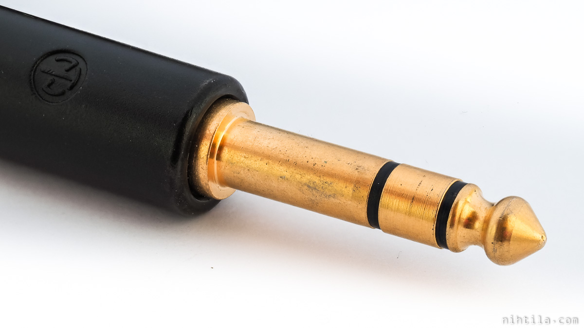
Cable may have separate or shared ground conductors but ground is shared at least in the 3-pin plug
Simple analysis of common-impedance coupling
See the illustration below I drew when thinking about this problem. We have two amplifiers, L and R with output resistance 1 Ω. Signal then goes through headphone jack with a small resistance, here 0.1 Ω on each contact. Then we have headphone cable (which also has finite resistance but is ignored here) and 32 Ω headphones. In this case the headphone cable has separate ground leads for each channels but there may be only one common coming from the speakers. Anyway, even if separate they are tied together in the connector. Effectively we have separate circuit for left and right channel but they have common ground impedance due to single ground conductor in the connector.
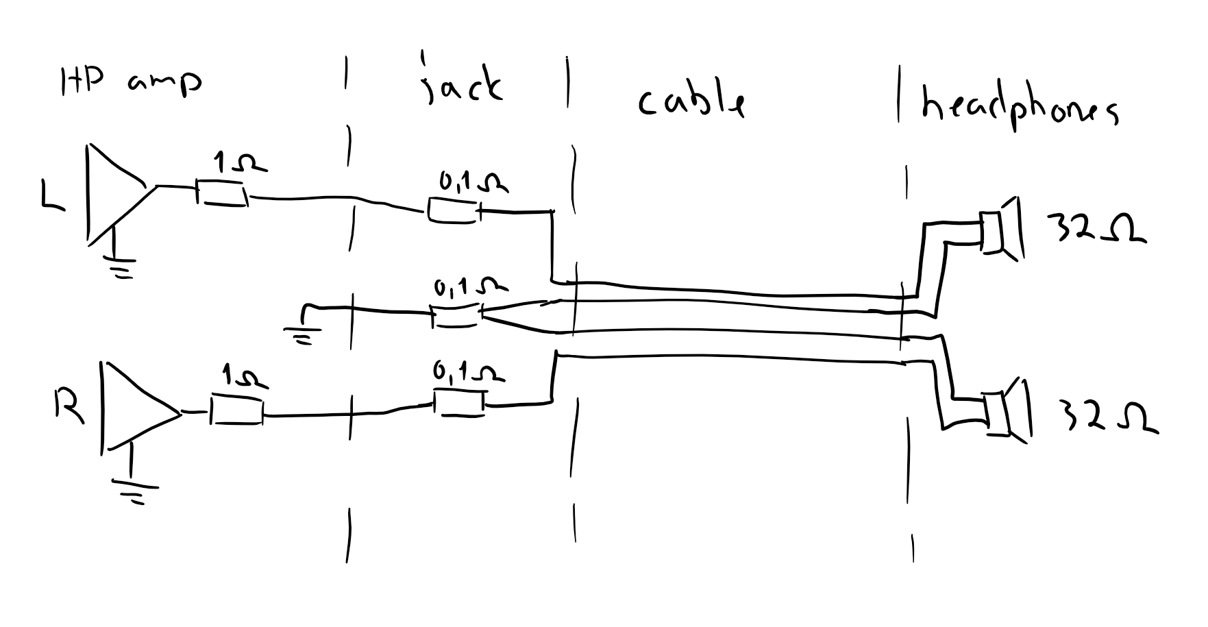
Illustration of unbalanced headphone connection
Now let’s play 1 V signal on the left channel, while right is undriven, illustrated below. In the circuit from left amplifier output to speaker and back to ground this 1 V signal causes 30.1 mA current to flow. This current causes 3 mV voltage drop in the 0.1 Ω common ground impedance. If we now look at the right channel circuit (that is not playing anything so output is at ground potential), this 3 mV appears as signal there, causing current to flow in the right channel circuit. Given that speaker impedance is much higher than the other impedances in the circuit, this 3 mV signal can be seen in the speaker. While it is small compared to 1 V signal in the left channel, in terms of crosstalk the ratio is poor: around -50 in decibels. This is also the ratio of speaker impedance to common ground impedance.
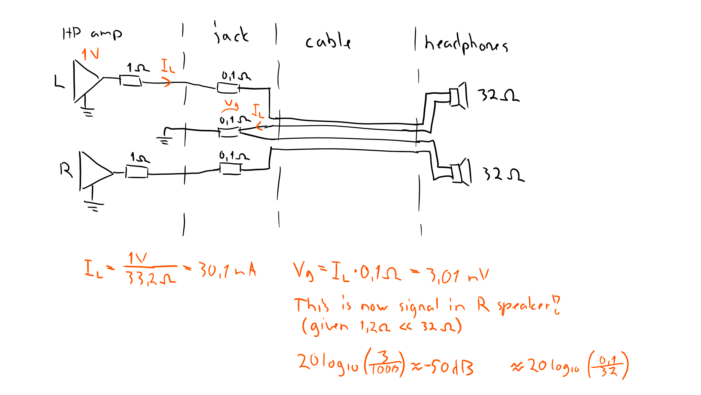
Signal driven on left channel in unbalanced headphone example
I just came up with these numbers but they are actually quite close to the measurements done on Modular HP Amp.
When headphone impedance changes, current and crosstalk change as well. Again, this can be seen as ratio of headphone impedance and common-ground impedance – halving the headphone impedance to 16 Ω causes 6 dB increase in crosstalk.
When we use balanced interconnection with separate return current path for each channel, there is no common ground impedance and common-ground coupling does not occur. This does not require driving both hot and cold leads, amplifier can even be designed in single-ended manner but signal routing must be such that there is no common ground. Typically this means routing the return signal path to the corresponding amplifier ground reference.
In fact, getting rid of common-ground coupling does not even require impedance balance, just separate ground return paths. However, impedance balance brings the benefits of immunity to noise and interference.
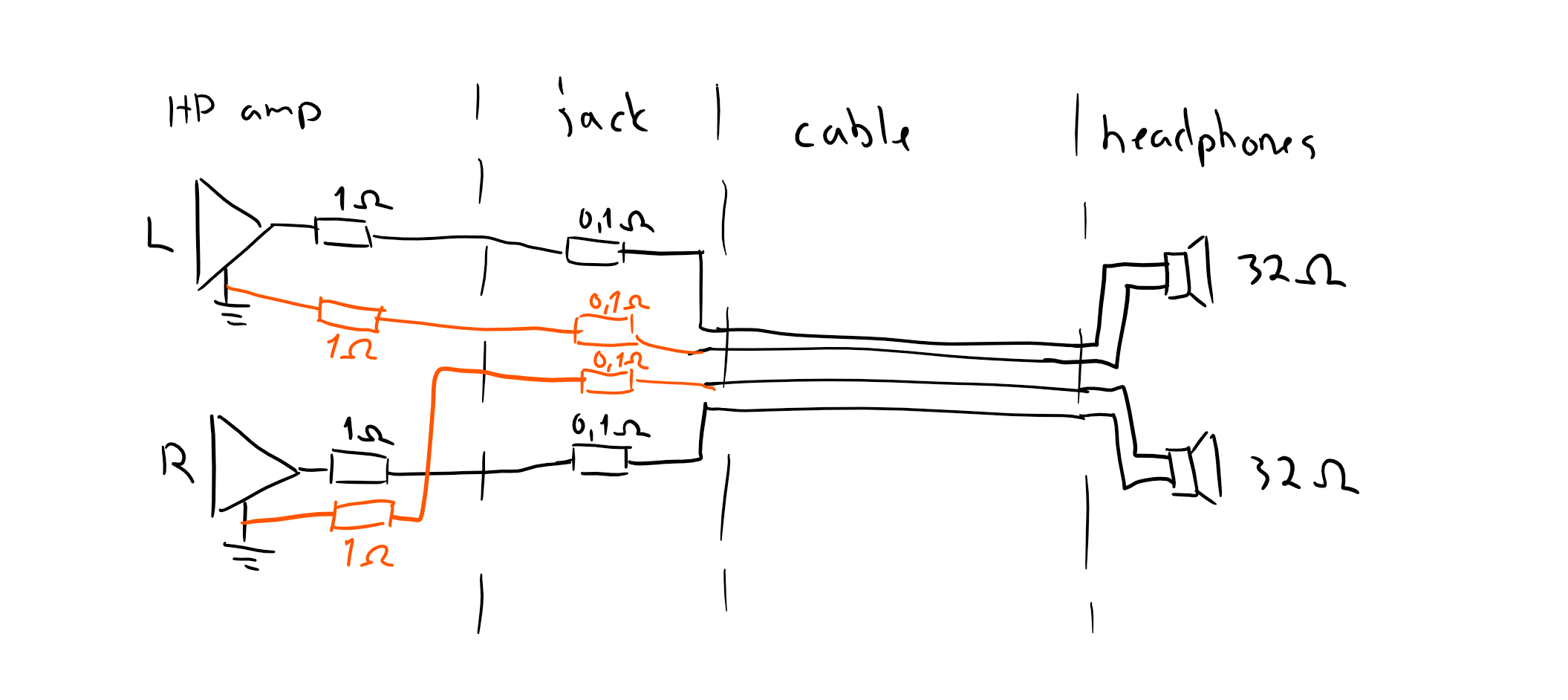
Illustration of balanced headphone interconnection
Crosstalk measurements
To support all this hype about the superior balanced headphone connection, I have done some measurements on my HP Mobo and HP Buf amplifier.
Below are crosstalk sweeps into 32 Ω load, using unbalanced and balanced outputs. Quite a difference, huh?
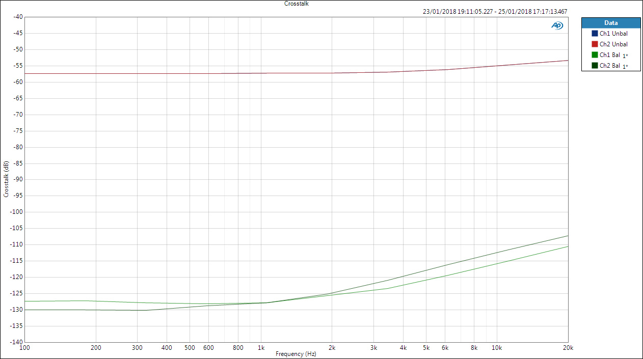
Crosstalk comparison between unbalanced and balanced outputs into 32 Ω load
For 16 Ω the difference is even bigger as larger current causes larger signal in the common ground impedance. Correspondingly, into high-impedance load of 300 Ω the difference is smaller.
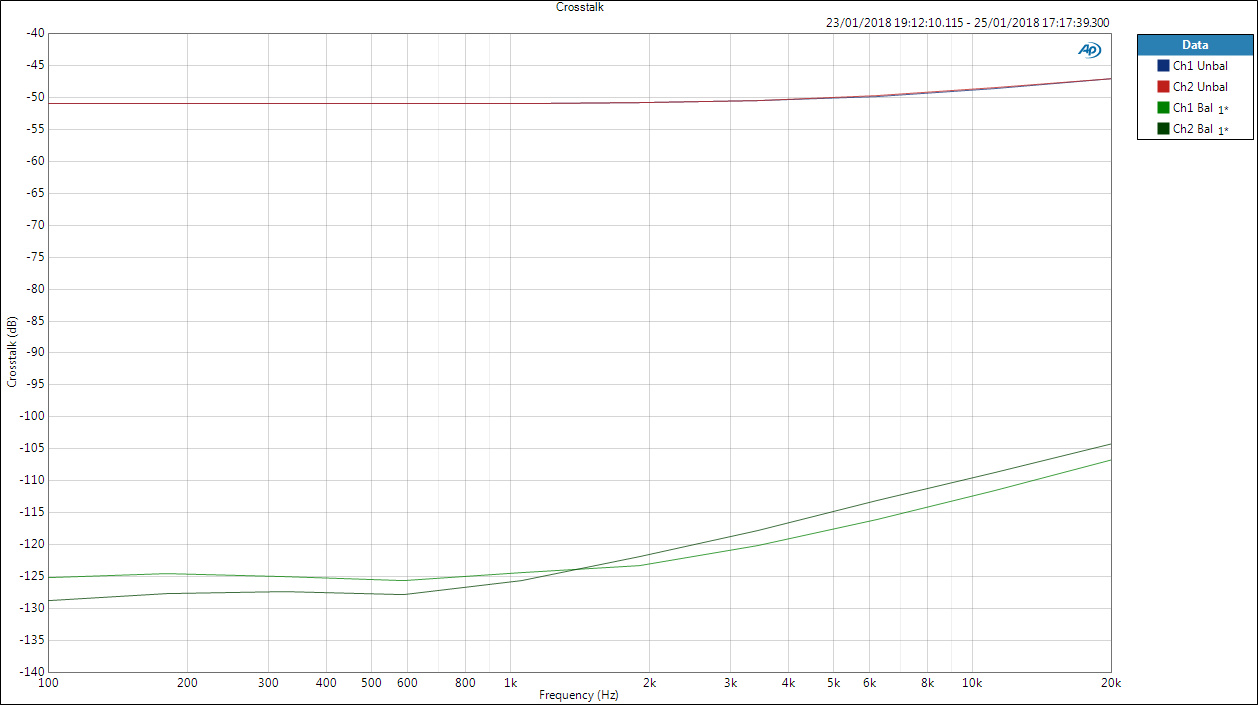
Crosstalk comparison between unbalanced and balanced outputs into 16 Ω load
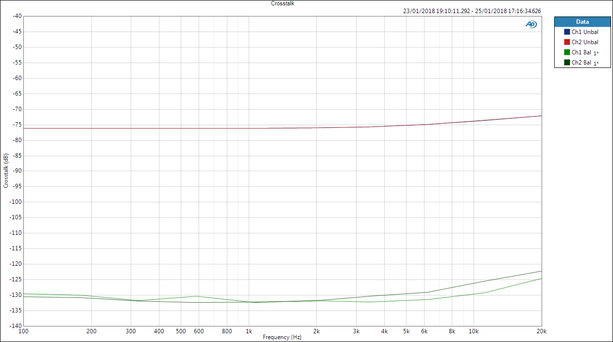
Crosstalk comparison between unbalanced and balanced outputs into 300 Ω load
As mentioned in the analysis above, crosstalk is determined by the ratio of the load (headphone) impedance and the common ground impedance. Knowing that if Rg is the ground impedance and Rhp headphone impedance, crosstalk (dB) = 20*log10(Rg/Rhp). Using the figures from the graphs we can calculate that the common ground impedance is around 50 mΩ.
Sometimes ‘fully balanced’ designs where both hot and cold leads are driven by individual circuits are said to provide lower distortion and so on. This may be true as one amp gets effectively easier load to drive and slew rate is also doubled. However, these improvements would undoubtedly be smaller than the seen crosstalk figures and doubling the amplifier circuits has big impact on cost and complexity. However, I must say I have been thinking about designing such doubled version of the HP Buf to see if improvements could be measured. We’ll see..
Balanced headphone connections on commercial products
There are commercial headphone amplifiers with balanced outputs. However, there are no standards for the connectors so various options exist. Some amps use 4-pin XLRs and some two 3-pin XLRs (or XLR-6.3mm combo connectors). Also more exotic connectors can be seen. Of these 4-pin XLR seems to be the most popular. These connectors are female in the amp end, therefore opposite to common XLR convention.
Connectors at the headphone end are not standardised either. While 2.5mm plugs are used by few manufacturers, some use proprietary connectors. Connectors may have 2 or 3 conductors. Due to lack of standards, no headphones usually come with balanced cables in the box but require custom cables. As long as the headphones have individual conductors for both left and right speakers, balanced driving is possible.
Below is an example of a headphone amp offering basically all possible connections seen. It is a Cayin iHA-6 amplifier I just found on Google and know nothing about. There is a 4-pin XLR for balanced output as well as 2x 3-pin XLRs for balanced output so it offers both above-mentioned possibilities. In addition to that, the 3-pin XLR combo connectors have 6.3mm sockets for normal unbalanced output but one of them offers low-impedance output and the other high-impedance output. This is quite common in amps with two 3-pin XLRs for balanced output.
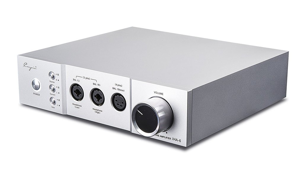
Cayin iHA-6 headphone amplifier with four different type of headphone outputs
When it comes to headphones, most higher end (read: more expensive) headphones have detachable cable. If there is separate connectors for both speakers, a custom cable can be made. See below my Hifiman HE-560 headphones and custom balanced cable I have made.
Note that the 4-pole 3.5mm TRRS plug used in headsets and mobile phones is not balanced, the extra pin is for microphone which again shares the ground conductor with left and right speakers, causing even more common-impedance related issues!
My DIY approach
I have designed my own modular headphone amplifier with support for balanced outputs. I also have headphones that can be driven with balanced interconnects.
Hifiman HE-560
I have Hifiman HE-560 headphones at the moment and the cable is detachable with 2.5mm plugs. As usual, the provided cable has a standard 6.3mm unbalanced connector so custom cable is needed for balanced driving.
I do not know why they use 2.5mm stereo connectors, signal is between tip and sleeve and ring is unconnected.
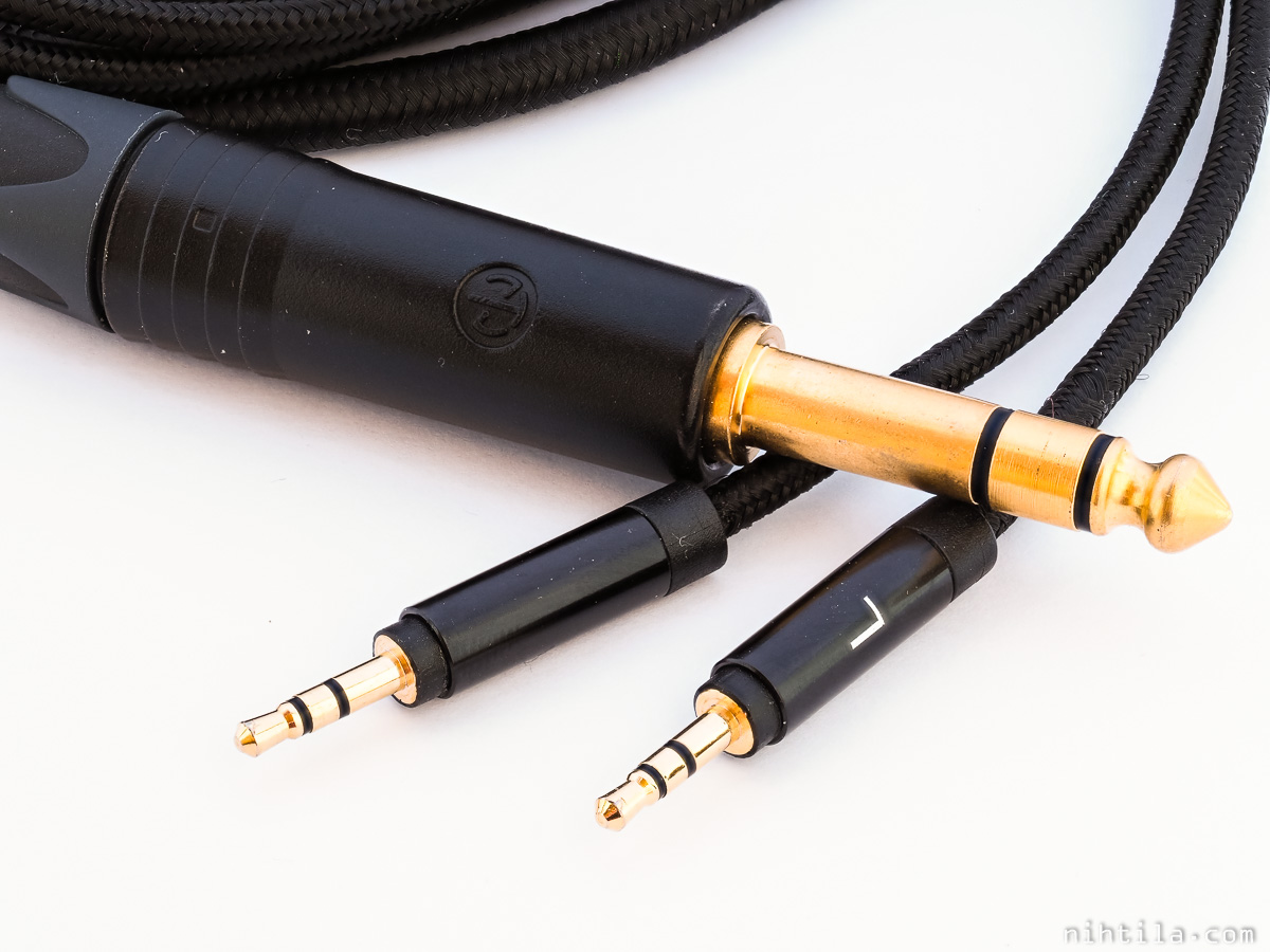
Hifiman HE-560 cable
I have made my own cable with 2.5mm plugs for headphones and 3-pin male XLRs for my amp. Unfortunately the 2.5mm slots on the headphones are very small so no standard connectors tend to fit in. That is why I needed to peel off the connectors so they look quite ugly.
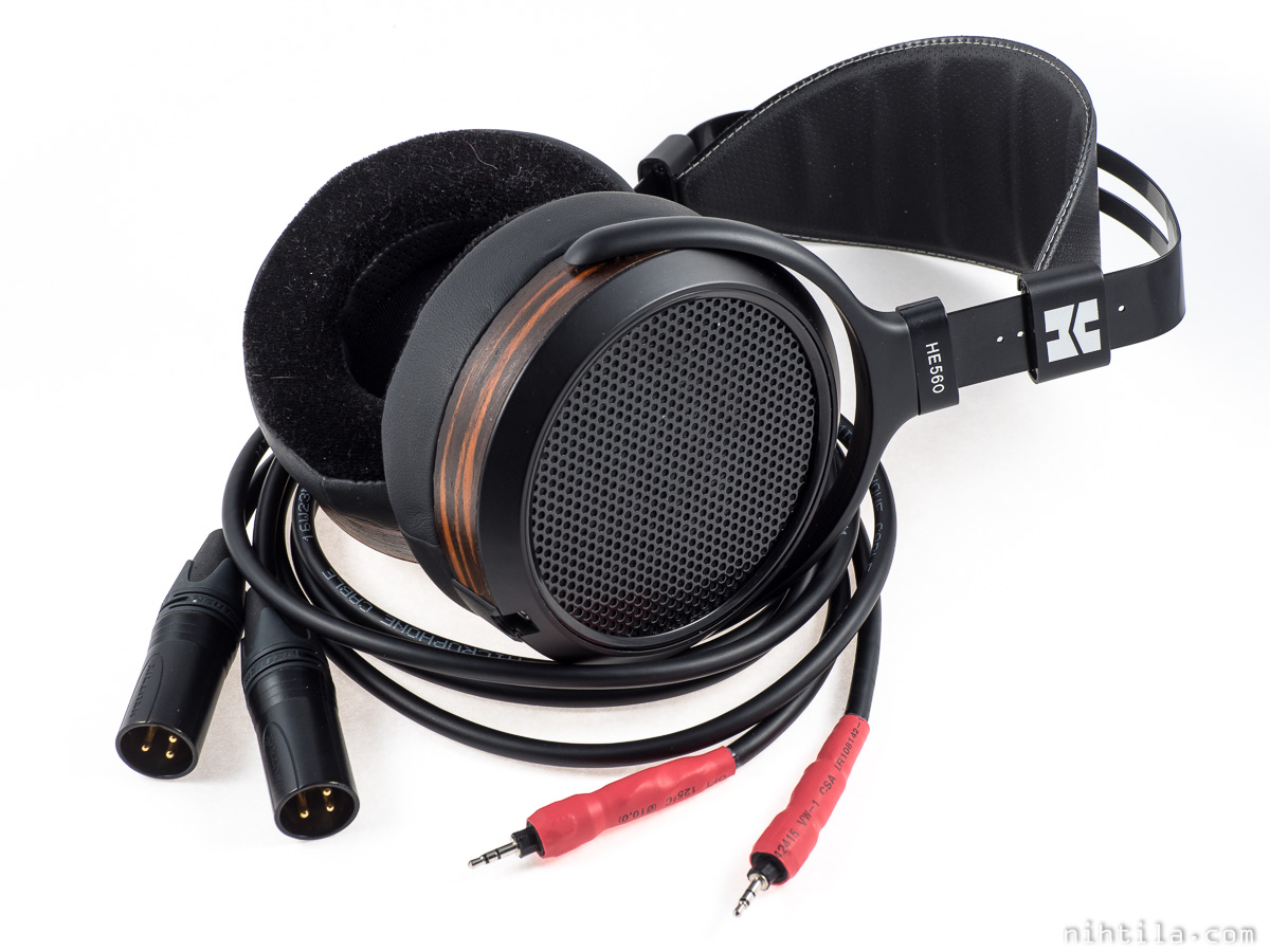
Hifiman HE-560 and my custom balanced cable
While 2x 3-pin XLR is nice to have cables completely separate, I must say that it is not the most practical as you have two relatively thick loose cables. I listen to my headphones at desktop and the cables are quite short so this does not really bother. One cable with 4-pin XLR would be easier to handle though.
HP Buf and HP TPA
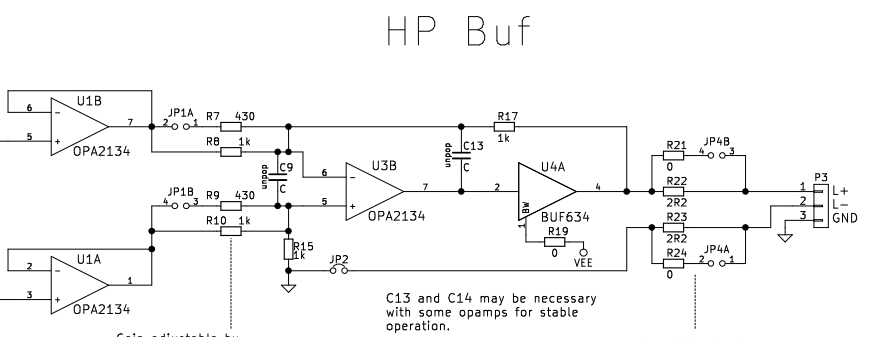
I have designed and built my own modular headphone amplifier, consisting of a motherboard HP MoBo and amplifier daughterboards HP Buf and HP TPA. HP MoBo supports both balanced and unbalanced outputs, where the latter is taken as positive balanced output leads and ground. The implementation on both amplifier boards is as described above as ‘simple balanced’ example where the cold lead is a ground connection through a series resistor.
Below is part of the circuit of one channel in HP Buf. Positive output is the output of BUF634 bufffer and negative output is a ground connection taken from amplifier ground reference point. There is a selector for the output impedance which is here 0 Ω or 2.2 Ω. One thing to note in such circuit is that this is not very well balanced, and poorly balanced if output resistor is 0 Ω. This is due to the fact that amplifier output impedance is not 0 Ω although it is very low in a circuit with high-gain amplifiers and negative feedback.
Such circuit gives a lot better balance in line-level circuits where series resistors are in the order of tens or 100 Ω. However, this circuit still gets rid of the common-ground connection of headphone amplifiers.
Overall thoughts on balanced interconnections in DIY
Shown simple balanced output is indeed very simple and good way to create balanced interconnections in DIY audio. You do not need to change anything in the circuit, just change the connectors and place a ground resistor. While I have used more complex actively driven balanced outputs in the past, recently I have started using this type of output which can be seen in Addon BalOut v2 and headphone amps HP Buf and HP TPA. The biggest issue with this type of connection is that other people and potential customers demand fully actively driven outputs because they think it is superior or do not understand the concept.
Conclusion
Although it has been shown crosstalk can be made 1000 (= 60 dB) times better by using balanced interconnections, obviously practical meaning is less significant. One valid argument is that we naturally hear things with both ears. ‘Crosstalk’ between your ears when listening to speakers in a room is almost 0 dB. Yet we strive to make the crosstalk of our system as good as possible up to speakers.
When listening to headphones, we can actually keep the channel separation extremely high all the way to ears if we want to. Some consider high channel separation unwanted in headphone-listening and use dedicated crossfeed to deliberately mix left and right channels for more ‘natural’ soundstage. Opinions all alike, yet at least I want to get the highest possible performance from a system. It is not often we can actually gain measurable improvement of tens of dBs with such small change in the system. However, inconvenience is that it requires system-level change: amplifier, headphones, and cables must be compatible. This does not mean the highest flexibility but luckily in DIY we can do almost anything.
Can you hear the difference? Channel separation improvement is huge so in extreme cases you may spot the difference. In practical music content probably not. But again, this is a significant technical improvement worth striving if the practical inconvenience of non-standard connectors and cables is not too great.
I have only addressed headphone connections here but balancing is more common in line-level signal connections. I recommend all DIYers using balanced connections as it is very effective way to get rid of ground loops and hum sometimes found in HiFi home gear. The mentioned simple balanced output using a ground resistor is very effective especially in line-level connections as larger series resistors can be used, giving better impedance balance.
References and additional information
Apparently this post already became quite long. Balancing is a wide subject, especially when considering analysis of noise pickup. The whole interconnection consists of output stage, cable, and input stage, and the balance of all parts affect overall performance. Moreover, I have only considered simple resistances when discussing impedance balance but in practice there are always capacitive and inductive components as well and as we have less control over those, that is where the equilibrium starts to fall apart when frequencies increase. For some mathematical analysis and more in-depth (but still easily understandable) explanation see Henry Ott’s Electromagnetic Compatibility Engineering book.
- Ott, H. W., Electromagnetic Compatilibity Engineering, John Wiley & Sons, 2009.
- One of the must-reads of electronics books
- Presonus (by Mike Rivers), “Balanced and unbalanced connections”
- Good explanation by a manufacturer of professional audio gear
- Headphone.com, “Balanced Headphones Guide”
- Nice diagrams and points out the common ground problem; however, as many they have got the definition of balanced wrong
- Rane Audio library
- Excellent source of technical information regarding interconnects, grounding, etc., for example:
If you have questions or comments, drop a line below.
3 comments
Thanks for a great post! Benchmark also has a nice article on this topic, but they don’t mention crosstalk improvements: https://benchmarkmedia.com/blogs/application_notes/audio-myth-balanced-headphone-outputs-are-better
Do you know what changes if the ground is driven (as in AMB M3 design?) From measurements done by Bob Katz (https://www.innerfidelity.com/content/katzs-corner-episode-8-my-current-affair) and myself (https://melp242.blogspot.com/2018/06/measuring-amb-m3-vs-spl-phonitor-mini.html) the channel separation is even worse than of a conventional “undriven ground” design, but I can’t extend your reasoning myself.
Thanks for the links!
I can agree with Benchmark. I wouldn’t be so much against driving the return actively but I can see their points and all they say are probably true. I would just put it in a way that driving both positive and negative is unnecessary, especially as it almost doubles the cost of electronics. Key thing is still to keep the return leads separated for left and right channel. Terminology can be confusing in these as there are no standard wording, they say “voltage-balanced” meaning when both signals are actively driven as opposed to single-ended. However, in that context single-ended is also using separate ground return cabling.
The active ground concept seems a bit odd to me given that one circuit drives the ground of both channels. Briefly thinking I don’t think it should change the crosstalk idea much as it is a matter of common impedance and current flowing through it (hence effectively a common voltage). So my quick conclusion would be that the impedance of this actively driven ground is higher than plain passive ground, effectively causing higher common mode voltage and reduced crosstalk.
Another great article! Clear explanation of a topic that gets tossed around a lot in headphone discussion, but is rarely well defined. I got a lot out of the circuit diagrams and calculations. Maybe because I am an engineer. 🙂 Thanks!
Comments are closed.