
Finally it seems W-DAC shows superb and most of all consistent performance across boards. I needed to have a break for a few months from all of this as I got quite frustrated after manufacturing a batch of boards and then not meeting the performance I’d seen in tests before.
Going after -115 dB THD+N
I’d like to say how I managed to find the root cause by extensive fancy measurements using the greatest of theories. But that’s not really the case. There was a lot of measurements indeed, but at the end of the day it was the good old trial and error method that worked.
Capacitance sensitivity
I have written about capacitor sensitivity of these boards before. Yet, after getting well performing boards I thought I got it. But after finalising five boards from the manufacturing batch, the performance was all over the place. None of them was as good as I had seen before, and the worst ones showed -96 dB THD+N while I was hoping to reach -115 dB. Then I was playing with capacitors; I placed several new capacitor placeholder on this PCB revision knowing that I may need to experiment. However, when something worked on one board, the results were not consistent when tried on other boards.
Power supply impedance measurements
After the break I tried a new approach – quantifying power supply impedance across frequency. I did a lot of measurement trying to use my Analog Discovery 2 but also Ridley Engineering AP300 impedance analyzer at my work. While I learned a lot about power supply impedance, impedance measurements, injection transformers and so on, after all I could not find a clear relation between my measurements and the audio performance I saw. It is probably somehow related to the supply impedance and measurable in some way, I was just not able to do it.
Back to cap swapping
So after trying more scientific engineering approach, I went back to full on trial and error method. I just took a loads of different capacitors: SMD ceramics in different packages, dielectrics and capacitance values, electrolytics, film caps, and so on, and started swapping them measuring performance in between. If something worked, I applied it to another board to see if results were consistent. Surprisingly this time I actually found a working combination relatively quickly, and got solid performance on all five test boards. I’m sure I had tried almost like that before but maybe not systematically enough. After all, even a small change may alter performance significantly.
The magic trick? Just place 10u 0603 ceramics in right places. And remove some 100n 0603 ceramics. In fact, replace some near-IC 100n caps with 10u, and add more 10u a bit farther away. That’s it. All of my five boards now showing -115 dB THD+N and flat THD+N vs. frequency. Add one more ceramic somewhere, or do not place a second 10u in the VREF and performance may come down significantly. Oddly sensitive. Five boards is still not a huge sample size but results looked very consistent so now I really believe I’ve got it!
As an example, here are three FFTs – compare the level of harmonics. The difference between these are just a different combination of 100n and 10u ceramic caps; and none are without caps. The difference in THD+N between the best and the worst are 18 dB.
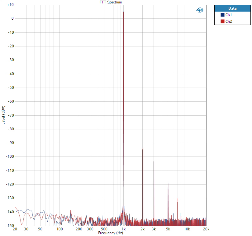
THD+N -98 dB
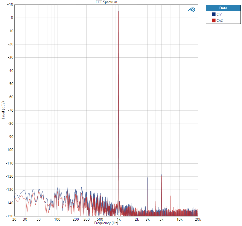
THD+N -112 dB
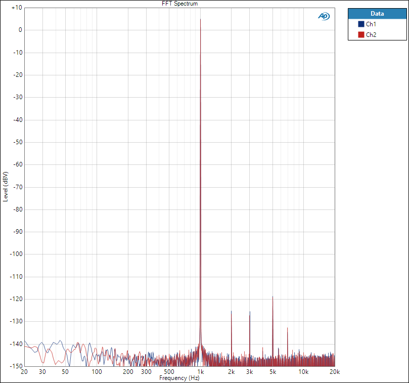
THD+N -116 dB
I still don’t know why the board is so sensitive to capacitance. I think it is related to both LT3042 regulator and the DAC. I have not seen as great capacitance sensitivity with other regulators. Or with other DACs or ADCs. But then again, LT3042 is a superb LDO and provides the best results. It may not like a lot of capacitance at the output which is also mentioned in the datasheet. For example, I use 1000u electrolytic in the AK4490 version but here adding a large cap often degrades the performance.
I know some others have used LT3042 with large capacitors with great results. And maybe not seen this sort of sensitivity to capacitance. So maybe it is something unique in my board or circuit, I don’t know. Anyway, this has been a good learning (if quite frustrating) and made me a better engineer – in testing, developing, measuring, and manufacturing boards. I hope the results remain this good and consistent.
Buy W-DAC 4493 here.
5 comments
>> ” In fact, replace some near-IC 100n caps with 10u, and add more 10u a bit farther away. That’s it. ”
that’s very interesting,
I’ve had a almost similar experience in an older DSP project some years ago …
is this new kind of cap arrangement already present in the latest schematics ? –> http://nihtila.com/wp-content/files/W-DAC_v13B_sch.pdf
e.g. I see in the schematic, that +5VA_L is filtered different that +5VA_R (different set of caps / +5VA_R still uses 100n near the DAC)
Nope! There is a mistake in the schematic, and I forgot to update the files. VCOM caps are still 100n + 100u, so C3 should be 100n. Then VREFs have 2x 10u, so C4 should be 10u. Good spotting, I changed wrong cap when I updated these 10u values.
First of these 10u is very close to the DAC and the second one is a few mm farther (so both quite close). You can see the second placeholder empty in the photos, partly inside the big elco footprint.
I just want to comment that I have also used the LT3042 low-noise regulator, and have seen inconsistent results particularly at lower output voltages. While it does appear to be a good part in many applications, I have seen it cause noise issues in the most demanding circuits.
Sorry I have missed your comment. That’s interesting to hear. What do you mean by the most demanding circuits? I have not actually actively measured the noise of the regulator, just noise of the audio system it supplies.
Comments are closed.