
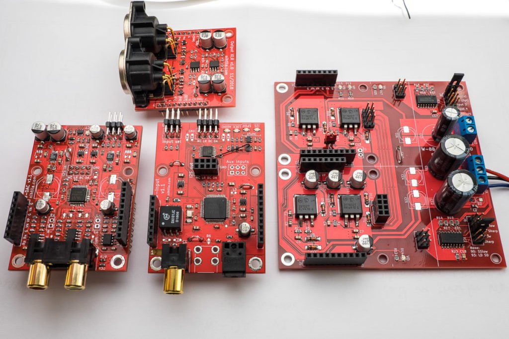
Measurements on slightly larger v1.1 boards:
- Superb performance using the best configuration, peaking at -112 dB to -114 dB THD+N
- Excellent performance using cheaper components
- Lots of changes on PCBs
Wee DAC development and measurements started with v1.0 boards followed by test boards measurements and now we have improved v1.1 boards ready.
Changes in v1.1 boards
There has been significant changes in the W-DAC PCB but also in system level.
W-DAC v1.1
Here are some of the changes in W-DAC PCB:
- Enlarged boards from 50×50 mm to 70×50 mm to make space for all changes
- Changed power supply scheme – now all regulators except ±15 V are on-board
- Two LDO options for analog 5 V: LT3042 or LP2992 (or any similar package)
- Room for large electrolytic at VREF
- Added support for AK4493
- Board-to-board interface changed
- Improved reset circuit
W-Input v1.1
Digital input board also changed in size and adapted lots of changes:
- 70×50 mm PCB
- Added external I2S input
- Added support for two more SPDIF inputs
- On-board regulators
- Board-to-board interface changed
- Improved reset circuit
System level changes
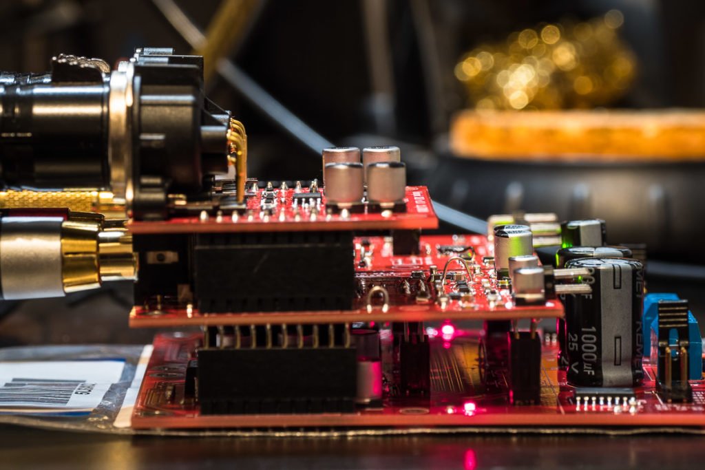
The whole Wee DAC system becomes more flexible with added I2S input on W-Input along with option for two more SPDIF inputs. While multi-channel I2S DAC using several W-DAC boards remains one application, high-performance stereo DAC with I2S and SPDIF inputs is clearly another. To better support this, a horizontal base board was developed where W-Input and W-DAC are next to one another instead of a vertical stack. This would likely be the preferred orientation for stereo DAC. In addition, there will be an option to add the two extra SPDIF inputs on top of the W-Input. It may seem a bit of a jigsaw puzzle but I like my modular designs.
More information on how to use the boards in a system is coming later on.
Performance measurements on v1.1 boards
After test board measurements, changes were applied to the W-DAC PCB to create the new version. Unfortunately not all measurements are as good as on the test board but most importantly the best performance is still achievable.
AK4490 and LT3042
As previously, this provides the highest performance:
- THD+N 1 kHz 0 dBFS: -114 dB
- THD+N 100 Hz 0 dBFS: -113 dB
THD+N vs frequency is basically flat.
LT3042 does not like excess capacitance at the output so using those 1000-3000 μF electrolytics is not recommended as it often deteriorates the performance. I have used 10-47 μF ceramics.
Note that -114 dB is a superb result. Especially considering the spec for AK4490 is -112 dB! Therefore, this will most probably not be consistently achievable across devices/boards. In fact, the -112 dB is a typical spec, while maximum spec is -105 dB. Only measuring more devices from different wafers over time will show how consistent this is. But at least it shows the design is capable of achieving such figure.
AK4490 and LP2992
This is where the measurements slightly fall short of the test board measurements:
- THD+N 1 kHz 0 dBFS: down to -108 dB
- THD+N 100 Hz 0 dBFS: -98 dB
THD+N at 1 kHz vary from -101 dB to -108 dB depending on the capacitor arrangement. And this has proven to be a complicated topic. Overall, extra (electrolytic) capacitance brings improvements here. However, it also matters what ceramics are in the same rail and so on. Also an LDO noise bypass capacitor matters here.
-108 dB is an excellent result here, achievable with big and expensive electrolytic; the only downside is that THD+N increases at lower frequencies – the same phenomenon seen in the first measurements. But not as much on the test board. I will need to spend a bit more time on that – or just accept it as LT3042 does not have this issue anyway. It is a strange one as the layout in terms of LDO and connections to AK4490 are not that different on the test board; overall this board is of course a lot more complicated.
AK4493
On test board just replacing AK4490 with AK4493 improved results. Here it did not. Therefore, I need to spend a bit more time on that later on. For now I will focus on AK4490.
Dynamic range
Dynamic range is consistently 119 dBA in all measurements. It’s slightly lower than test board measurements because it did not have the full output stage. I will carry on a couple of tests, for example lowering the resistor values, to get to 120 dBA which is a great round figure to have.
Getting significantly over 120 dBA starts to get trickier even if the DAC was able to support that. By using low resistor values and the quietest opamps does lower the noise floor slightly, and changing output stage architecture can improve it further but with trade-offs. However, it quickly gets close to physical limitations as well. To really utilise the dynamic range of 125+ dBA some DACs advertise, one needs higher signal level. It becomes a bit of a marketing gimmick unless you can really use a signal level of 4 V or 8 V in the system. The full-scale output level of W-DAC is 2 Vrms.
Conclusions
The more I measure, the more I notice how small things can have ‘big’ impact on performance (it’s not really big as we are under -100 dB but relatively speaking big difference). At the end I need excellent performance but also consistent and repeatable results if I want to make a production batch. But we’re getting close. I will carry out a bit more tests, also on a system level. A couple of small changes are required on PCBs but I don’t want to change much anymore after achieving excellent performance now.
Now looking at the first measurements on v1.0 boards: without any modifications the THD+N figure was -93 dB. We’ve come quite a long way from that!
I have been also carrying out listening tests and pop and click tests alongside technical measurements. I will keep things here technical as that is the only objective way to evaluate these circuits. I still believe getting the lowest distortion and noise is the way to solid transparent device and high fidelity. Colouring to taste can be done elsewhere in the sound system.
7 comments
It’s a pity that there is no USB interface.
You can get USB to COAX or SPDIFF on the cheap so it’s not like it is a huge issue.
Yeah, the issue is there are no simple one-IC hardware solutions for high resolution audio, only 16-bit 48kHz. All these XMOS etc stuff goes beyond my expertise; I’d like to investigate once what would it need to make my own USB interface. However, now the solution is to offer an I2S input where USB-to-I2S module can be plugged.
How expensive are these boars for you? PCB, components, etc.
It’s the biggest barrier I have that’s stopping me from trying stuff like this.
PCBs themselves are cheap these days, 2-layer boards cost almost nothing, 4-layer still something. And when ordering from China, taxes and shipping cost approximately the same as the boards.
Components.. of course they add up as well. Although my PCBs and components are nothing super expensive, every order from Elecrow/Mouser/Digikey is around £100-150 and I’ve made 10+ orders so things do add up… But it’s been a big learning experience. I hope I can get the money back by selling boards eventually but it can be difficult to actually make money. Maybe one day.
But if you start with something simpler and stick with 2-layer boards things don’t get awfully expensive.
Have you ever ordered from jlcpcb? They should be almost free. Only the shipping cost a lot.
No I have not. Looks cheap, especially 6-layer boards are very cheap! Unfortunately that’s often the case that you easily pay more for shipping than PCBs. That’s why I usually collect few different designs to order at once.
Comments are closed.