
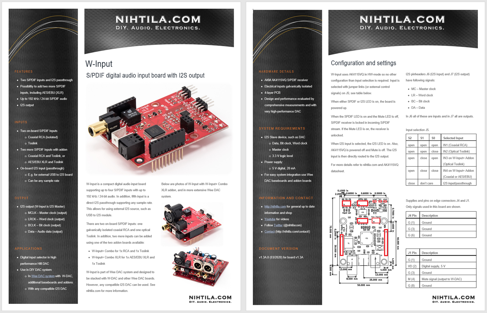
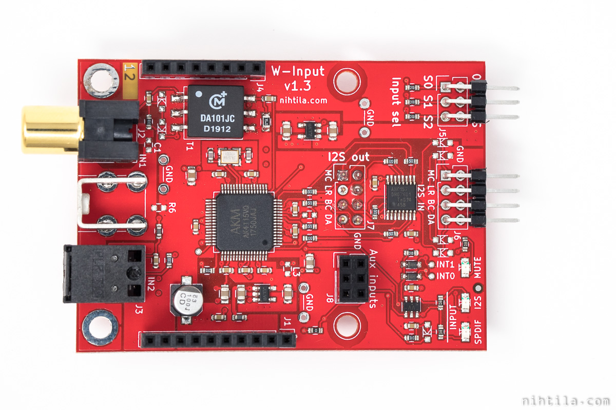
- Flexible digital input board combines I2S input and S/PDIF inputs
- One I2S input / passthrough
- One Toslink S/PDIF input
- One isolated coaxial S/PDIF input
- More inputs (Toslink / Coax / AES/EBU) can be added with addon board
- I2S output (up to 192 kHz / 24-bit from S/PDIF)
- High performance to match with high performance DACs
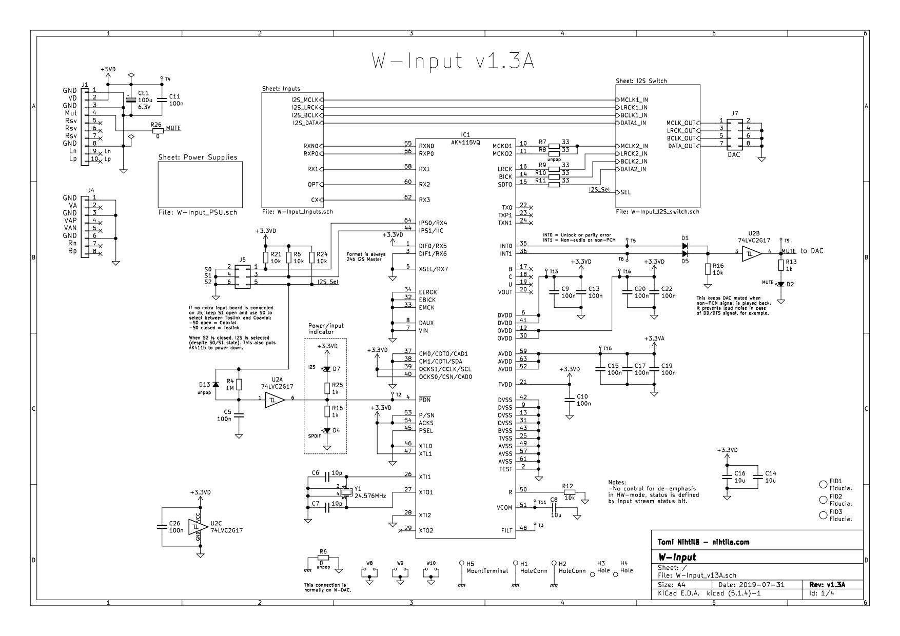
- AK4115VQ S/PDIF receiver
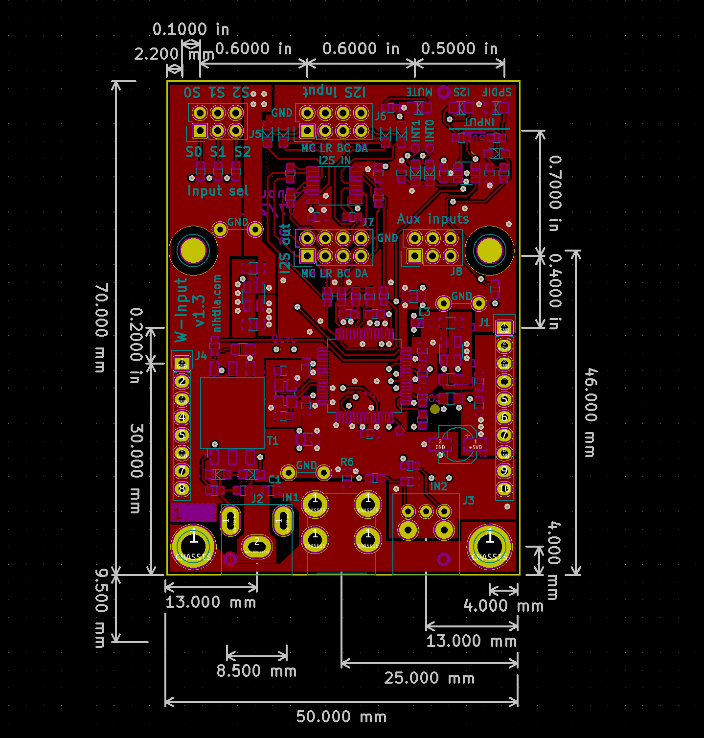
- Compact size at 70 mm x 50 mm
- Can be used with W-DAC or any compatible I2S-input DAC
- Wee DAC ecosystem offers numerous compatible boards
- S/PDIF input addon boards (Coax, Toslink, AES/EBU)
- DAC with balanced XLR addon
- Baseboards with or without power supply
- Assembled boards available
W-Input was designed as part of Wee DAC ecosystem but it can be used in any system providing needed supplies and compatible I2S signals. By using other Wee DAC boards, complete DAC with extensive digital input options as well as balanced XLR outputs can be built.
Below is a 2-page factsheet (PDF) showing key figures and features.
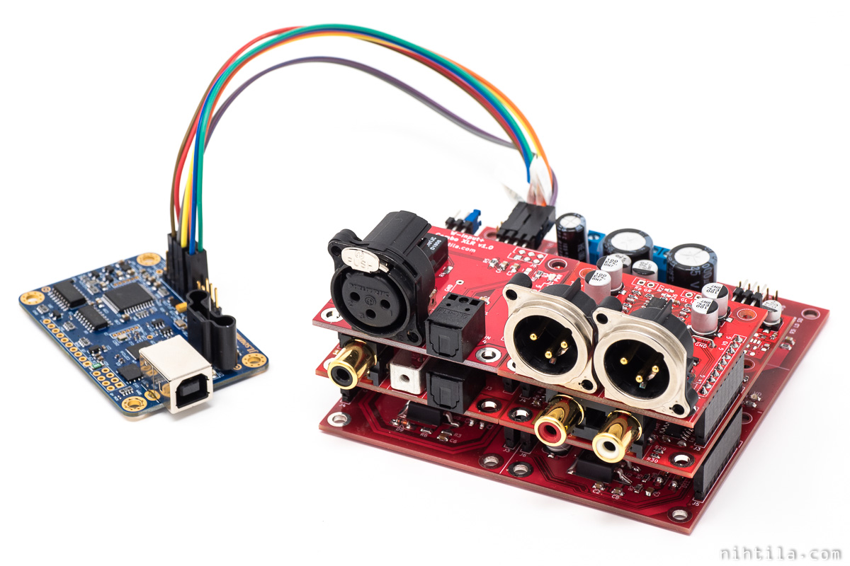
W-Input used with other Wee DAC boards and JLSounds USB module
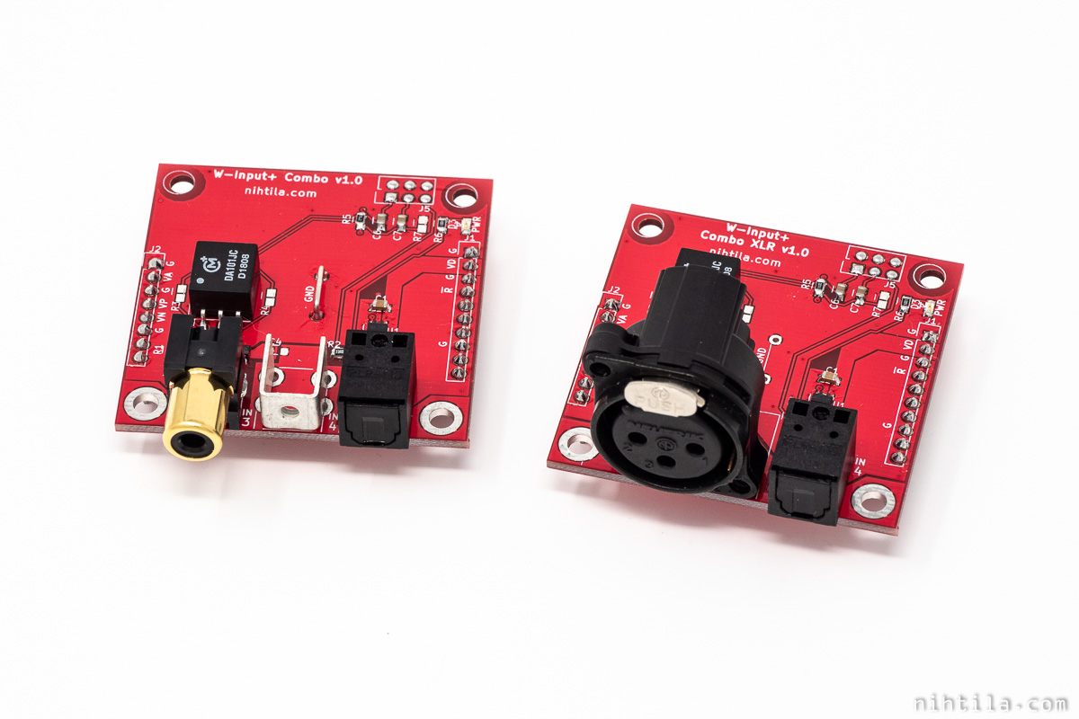
Extra inputs can be added with addon boards (only one can be used at a time)

W-Input with W-Input+ Combo XLR addon board
Design
As this is still more hobby than a side business and I have learned a lot by investigating others’ schematics, I have decided to release W-Input schematics. I won’t go into great detail of each component and approach for now but some development can be found in Wee DAC update posts. There also may be slight changes due to last minute tweaking or production reasons.
First of all, the role of W-Input in a complete DAC system (whether it’s Wee DAC or something else) can be illustrated in Wee DAC block diagram below. It has I2S input and S/PDIF inputs, and I2S output; basically it is an input selector.
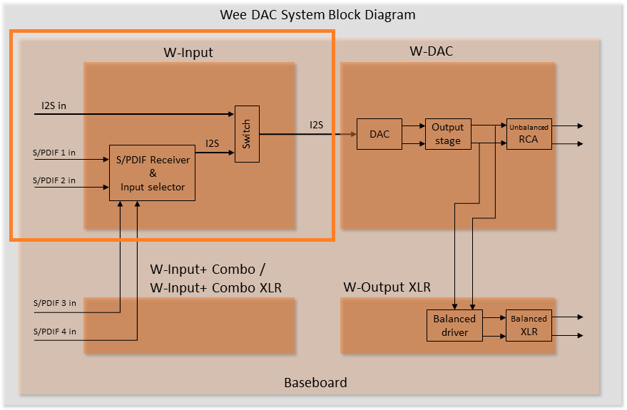
W-Input highlighted in Wee DAC system diagram
S/PDIF receiver
AKM AK4115VQ is the heart of this board used for decoding S/PDIF bit streams to I2S output. The chip automatically locks its PLL to incoming signal using provided crystal oscillator. Therefore, no settings are needed as it’s also used in parallel/HW control mode.
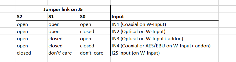
The only selection to user is input selection pinheader J5. Four S/PDIF inputs or I2S can be selected here; two inputs are on W-Input and another two can be added with W-Input+ addon board. When I2S is selected, AK4115VQ is powered down. LEDs are used in the power down input to indicate power is on but also whether I2S or S/PDIF input is selected.
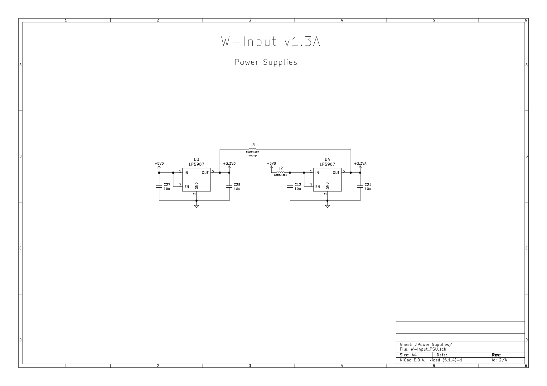
Power supplies
Two LP5907 LDOs are used for 3.3 V digital and 3.3 V analog (PLL).
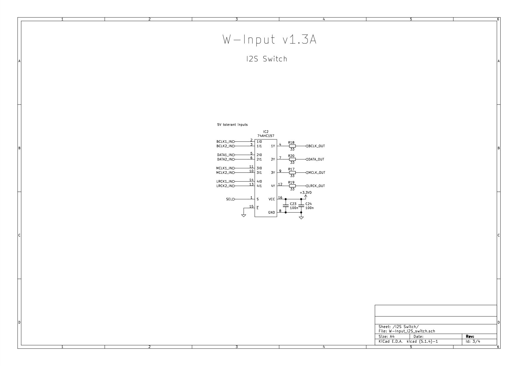
I2S switch
Simple logic IC, quad 2-input multiplexer, is used as a switch between direct I2S input and I2S coming from AK4115VQ.
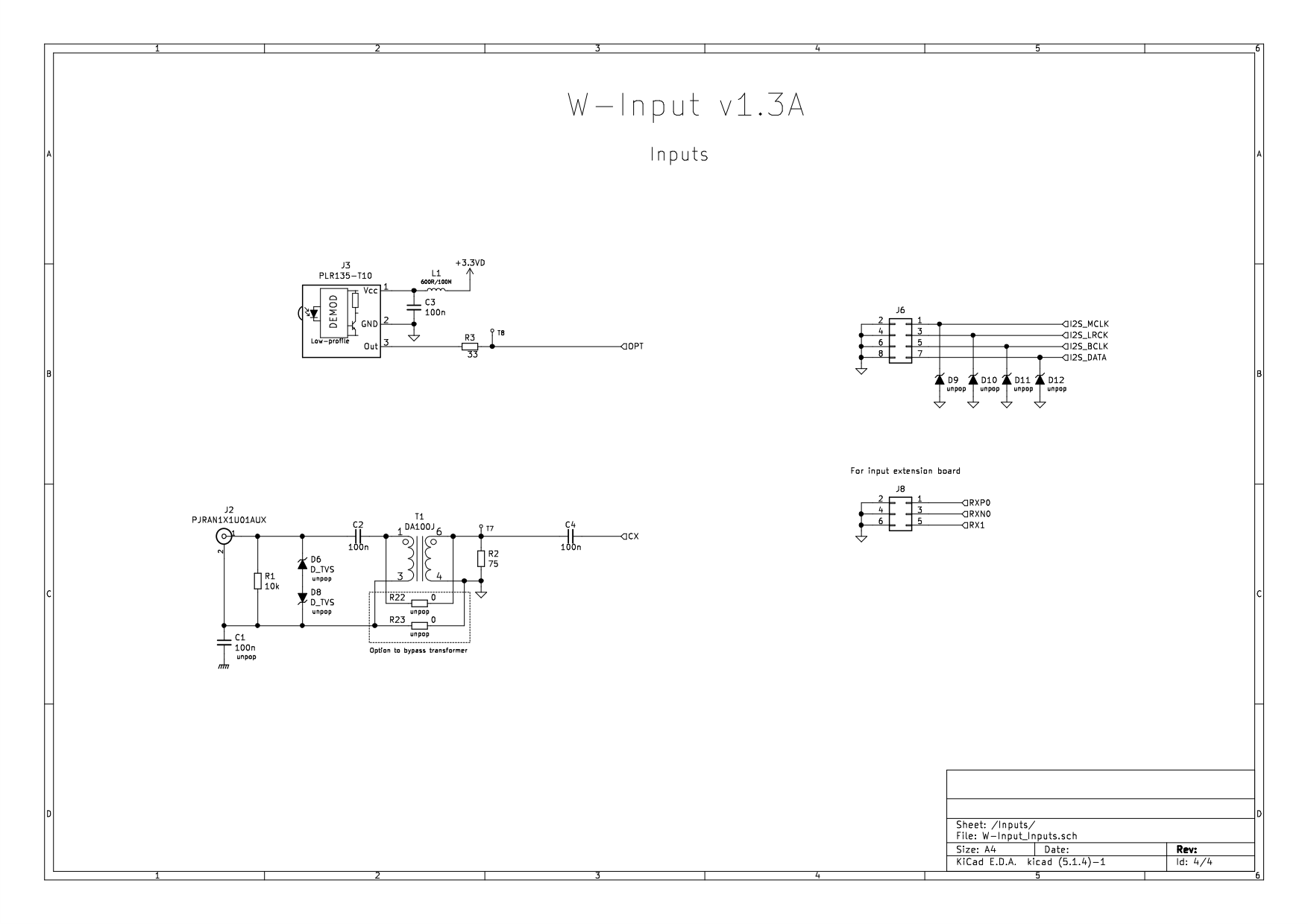
Inputs
There are one Toslink S/PDIF input and one transformer isolated coaxial S/PDIF input onboard. In addition, there is a pinheader J8 for two extra S/PDIF inputs using one of the Input+ addon boards.
I2S input is routed directly to the I2S switch.
No USB input?
No, there is no USB input simply because creating a high-resolution USB input is not a simple drop-in IC solution. Implementing an XMOS chip with dedicated firmware here would have been too big (and probably expensive task). I would want to investigate that option later but for now the solution was to add I2S input for external USB to I2S module.
PCB
PCB is 50 mm x 70 mm 4-layer board. PCB is one of the most important components of any design and in order to achieve great performance in such a small form factor, 4 layers were used here.
Schematics and layout have been done with KiCad and components sourced from Mouser and Digikey. PCBs are from Elecrow.
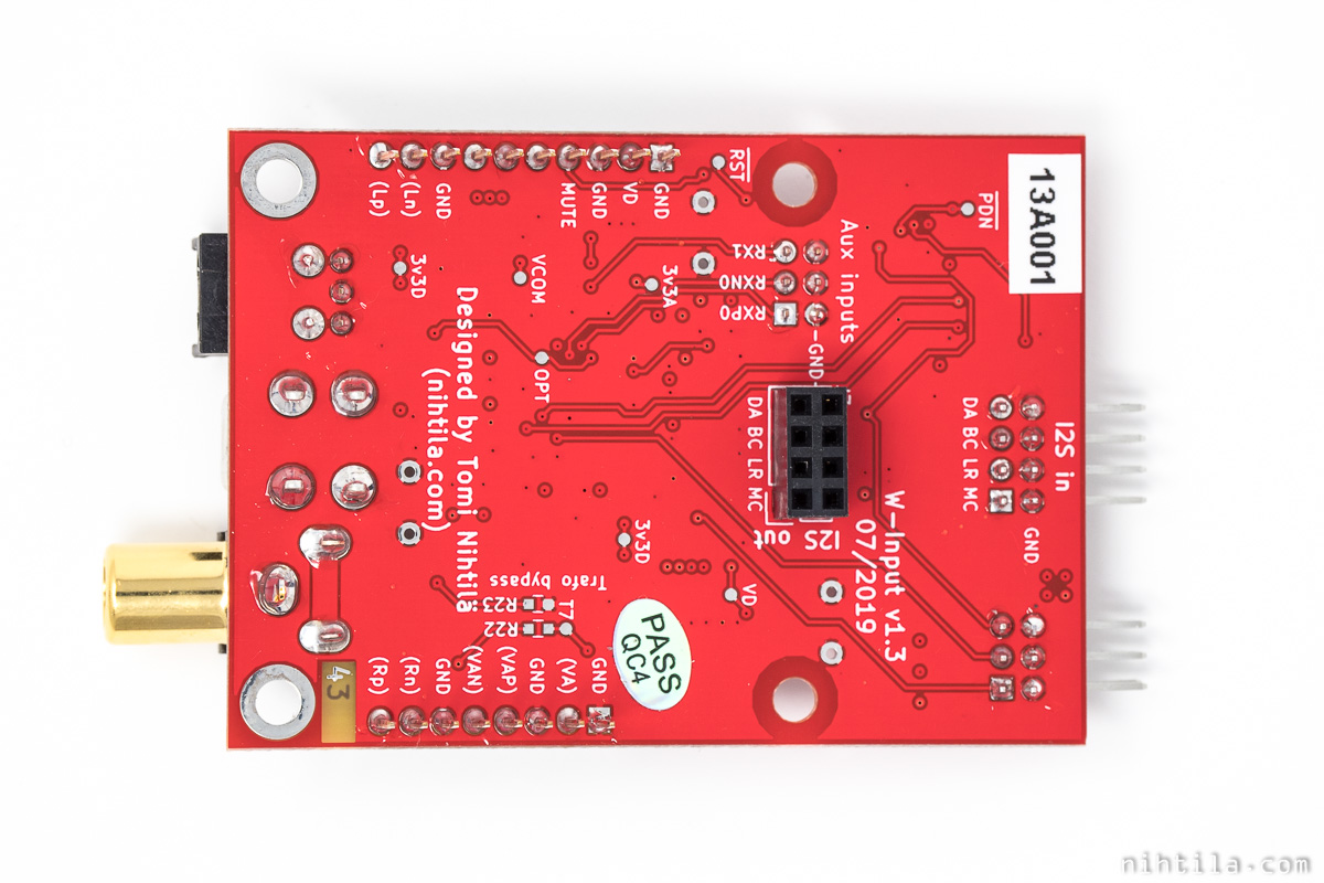
J7 on horizontal vs. vertical stack
There are various baseboards available and depending on that I2S pinheader J7 should be soldered on top or bottom, as shown below. Top placement is needed in vertical stack where W-DAC is on top of W-Input. Bottom placement is for all Dual baseboards.

I2S pinheader J7 is soldered on top or bottom side depending how W-Input is connected in the system
Configuration and settings
AK4115VQ is used in hardware/parallel mode so only setting to the user is selecting input:
Supplies
Supplies are provided on edge Wee DAC pinheaders. Note that there is no protection against over-voltage or reverse voltage; if you are unsure connecting please use a dedicated Wee DAC baseboard.
W-Input only uses VD supply:
- VD: 5 V, 20 mA
This is with 48 kHz signal and it may get higher with higher sample rates.
VD cannot be higher than 5.5 V due to LP5907 limit.
I2S input
I2S signal is routed directly to W-DAC and requirements depend on that.
Measurements
Several measurements have been carried out on this board but there is not much relevant to show. After all, the best praise for this board is that it has no impact on system performance. And this is the case even with very high performance DACs.
However, to ensure correct operation following tests have been carried out:
- Functional tests with 44.1 kHz, 48 kHz, 96 kHz, and 192 kHz sample rates
- Signal integrity measurements on S/PDIF and I2S signals; also ensuring S/PDIF transformer does not compromise signal quality
- Functional tests of reset and mute circuits
- Functional test of all inputs, including W-Input+ addons
Impact on audio performance
I have not seen this board being a bottleneck of a complete DAC system, and that is perhaps the best measurements result possible for a board like this. I have measured a DAC up to -115 dB THD+N and -115 dBV RMS noise floor, comparing DAC I2S input and W-Input, and noticed no difference between the two.
Files
I’ll do my best to keep these files up to date if something changes but there is no absolute guarantee. However, these do represent a working v1.3A initial release so there won’t be major changes.
- v1.3A files
References and additional information
Version history
Schematics / PCB version history and known errors and bugs
- v1.3A First released version
This page version history
- 5.11.2019 Initial version
- 27.3.2020 Added 2-page factsheet
I may have missed something important here. If you have more questions about this board, please comment below or send an email.
Buy W-Input here.
4 comments
Hey Tomi, I need a SPDIF to I2s Converter whioch deliver the clocksignals independent from a connected Input Medium.
I have already a converter which runs as Master for the connected ADAU 1701 and my raspberry. But it delivers only the Clocksignals if the CD player is connectet and the Cd -Player Power is on. Unfortunatly the cd-plyer turns itself down after 15 Minutes without playing a CD) so my whole system is without clocksignal.
1.Can your SPDF to I2s Card deliver a steady, (from the Input-Source-Powerstatus independant), Clocksignal? 2. Can your spdif to I2S Card work as slave. (Master will be than my ADAU1701 with 96Khz) Best Greeting from Hamburg, Thomas
Hmm, I’m afraid that may not be possible without some additional clock circuit and switching. SPDIF contains data and clock in one so receiver must always extract both and naturally makes SPDIF receiver Master. SPDIF receivers don’t have their own clocks so if there is no incoming signal, they don’t output at least anything sensible – unless there is another external clock and it switches to that. Some more complex ICs may have that but mine doesn’t. With normal SPDIF receiver you would probably need a sample rate converter in between that could run as Slave on both sides.
Sry for my delayed answer, Thank you very much. Do have ?a Samplerate – Converter in mind for that purpose?
Hi Thomas. Not really. I did make a sample rate converter test board a couple years ago but never got further with it. Never say never but it is quite a special use board in a way and not widely needed – or even recommended. Whenever possible, it is better to do sample rate conversion “offline” in PC, streamer, or whatever source without the effect of real clock signals. But indeed one use case is when you need to change Master/Slave scheme.
Comments are closed.