This board is a software-controlled version of W-DAC 4493, plus a few tricks added to improve it’s practical performance and usability especially in preamplifier applications. Another new feature not possible in HW-controlled version is DSD support. Here are the new features summarised:
- I2C-controlled – requires a microcontroller (e.g. Arduino) or any I2C host for control firmware
- Control firmware is not provided but there are code snippets on how to get it up and running
- Note that I2C control is required to get any audio out of the DAC
- DSD support
- Automatic hardware output mute
- Very useful in preamp application to avoid pops at power-up and shutdown
- Hybrid volume control – digital volume and one-step relay attenuation
- Greatly improves performance in practical volume levels in preamp use
The old features still hold:
- The same superb performance:
- THD+N ratio: -115 dB (1 kHz -1 dBFS)
- THD ratio: -121 dB (1 kHz, -2 dBFS)
- Dynamic range / SNR: 121 dBA
- Crosstalk: -125 dB, 10 kHz
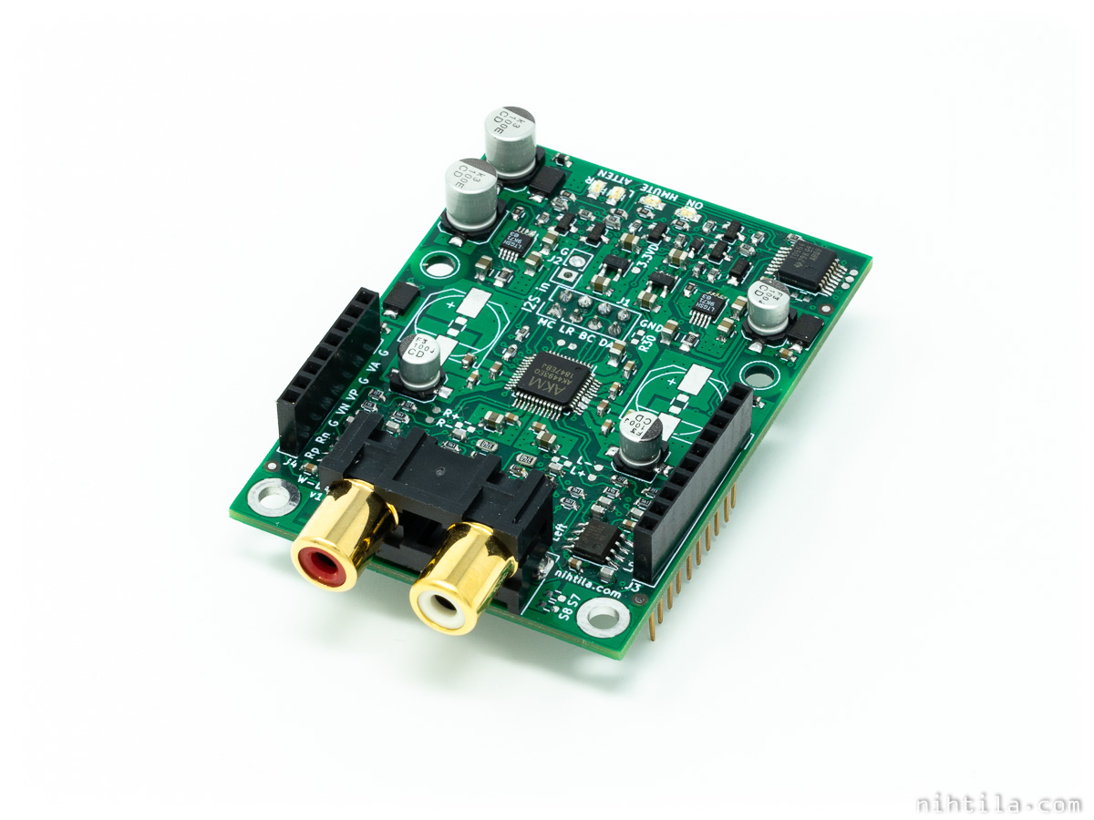
- Unbalanced RCA, 2 V output level
- Balanced addon available (now also with mute relay)
- I2S input, supports up to 32 bits and 768 kHz sample rate
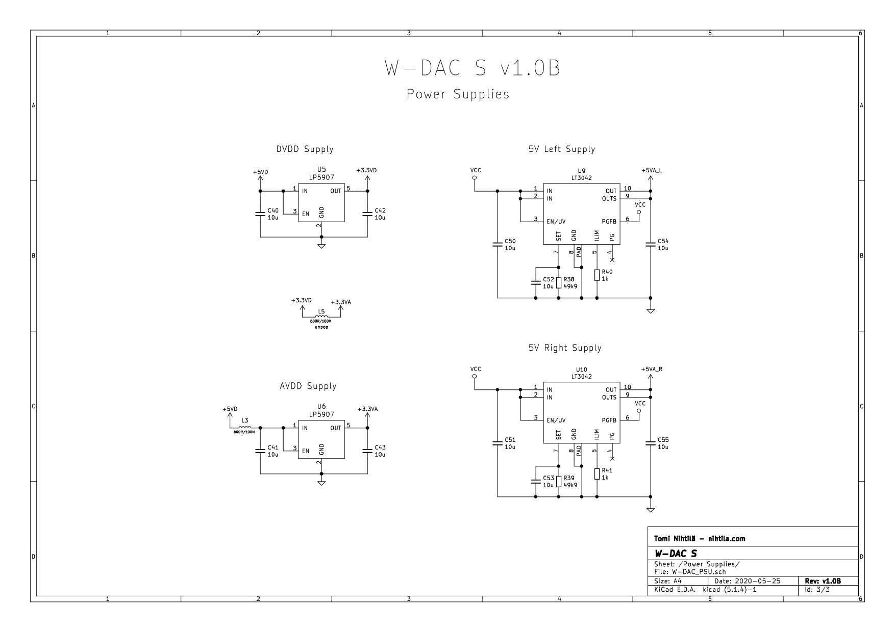
- AK4493EQ DAC, LM4562 opamps, LT3042 regulators
- Compact size at 70 mm x 50 mm
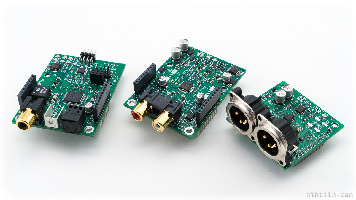
- Can be used with any compatible I2S source or in Wee DAC system
One limitation compared to old W-DAC PCB is that this one only supports AK4493, not AK4490 anymore.
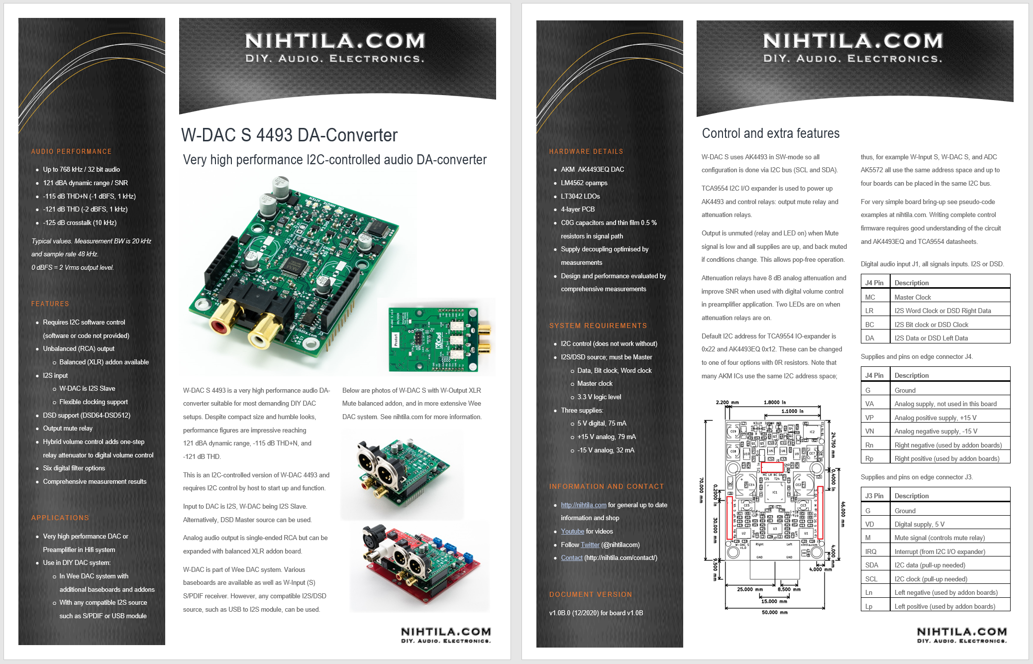
Below is a 2-page factsheet (PDF) showing key figures and features.
This board is part of Wee DAC system, find more here. Best matching components are W-Input S (I2C version of W-Input) and W-Output XLR Mute that adds output mute also in balanced output.
The main driving force behind the new features is the usability in preamplifier applications. With added output mute and volume control, one can build a very high performance preamplifier connecting the DAC directly to power amplifiers. Hybrid volume control helps to improve dynamic range at normal volume settings.
Design
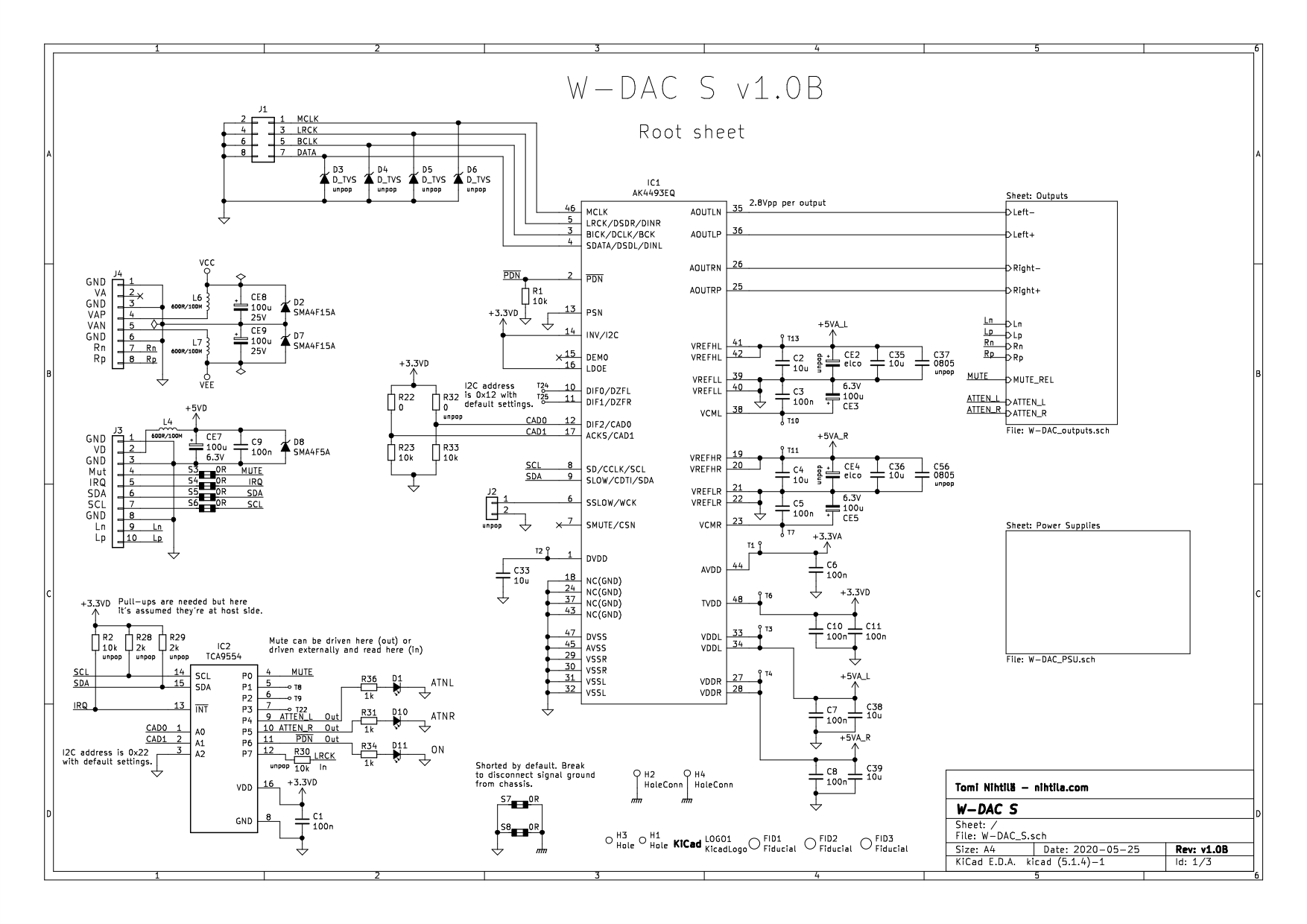
The design closely follows W-DAC 4493; the components and design around the DAC and output stage are the same despite slight changes in the output stage component values. Therefore, refer to W-DAC 4493 page for more info on the basic circuit. Here the focus is on new features and differences.
Control
Controlling is done via I2C signals SCL (clock) and SDA (data). Controlling AK4493 along with its register map is given in AK4493 datasheet. Moreover, there is also TCA9554 8-bit I2C I/O expander on-board to help control some of the other things outside the DAC chip. Default I2C addresses are shown in the schematics, and they can be changed with resistors. Four different addresses can be given to a W-DAC S 4493 board.
Note that W-DAC S has the same address space so four W-DAC S or W-Input S boards can be used in the same I2C bus. Also AK5572 used in ADC AK5572 is using the same address space; presumably most AKM ICs use the same address space.
TCA9554 is used for following functions:
- Power up DAC IC (PDN pin, high means power on)
- Mute signal (see more below)
- Attenuation relays (active high)
It is also possible to connect LRCK to one input and try to read sample rate when using I2S input; however, it has not been tested if this is really doable or practical.
Note that I2C and IRQ pull-up resistors are not populated by default, assuming that they are at the host side. Ensure pull-ups are in place somewhere in the system.
Mute signal
Mute signal is a bit more complicated as the system leaves various options how to use it. Mute is one of the fixed signals in the 1×10 edge pinheader along with SCL, SDA, and IRQ. The same mute signal is also there in non-I2C versions of W-Input and W-DAC. In those the source is W-Input.
Here you can also take Mute from W-Input (S), or you can drive it directly from the host, or you can take it from the TCA9554 here in W-DAC S. The choice is yours. But it is this mute signal that controls the output mute relay, and more of that below.
Output mute
One missing feature in W-DAC was a proper output mute. As output is directly connected to opamp, there will always be some sort of pop sound when power is turned on or off. The severity of this pop depends on power supply and what is connected after the DAC. There should always be a mute circuit somewhere in the system to avoid loud pops in speakers or headphones. Usually power amplifiers have this, and it’s ok for the rest of the circuit not to have it if everything is turned on in sequence or simultaneously; power amp keeps the outputs muted until everything is safe and sound.
As W-DAC S is designed to be in a preamp, or in fact be the preamp, reliable output mute is required. This is implemented by relay at the output that normally shorts the output to ground. There are four inputs the mute circuit monitors: the Mute control signal itself, +5VD supply, +15V supply, and -15V supply. Mute signal can be used to control the output Mute, but if any of the supplies is down, the mute stays on. Or if power is turned off, it mutes the output when supplies fall, despite the status of Mute signal.
If no manual mute control is needed, Mute signal can be tied to ground (or driven low from TCA9554) and then mute function just follows the supplies.
Note that there is also a matching XLR output addon, W-Output XLR Mute, that adds this mute circuit in the W-Output XLR board.

Power supply
After lots of experimenting with LDOs when developing W-DAC 4490 and W-DAC 4493, I have stayed away from all supply components and even traces on PCB. It was very sensitive in terms of LDO, decoupling capacitor style and placement, but when I got it working the results are consistent so didn’t want to touch that!
Hybrid volume control (..and a little about digital volume control in general)
Digital volume control is a great thing – it offers near perfect channel matching and crosstalk, no mechanical wear issues, and is cheap to implement; or in fact comes part of almost any digital audio circuit. It’s also the only practical option when channel count increases. Yet a lot of people tend to be against digital volume, which I frankly don’t really understand. Given the control itself is done well, there is really only one downside in digital volume control – fixed noise floor and its impact on dynamic range.
Consider your system and signal have 110 dB dynamic range that goes into volume control. Say at full volume your maximum output level is 0 dB (whatever is the reference level doesn’t matter here) and noise is at -110 dB. You turn volume to -6 dB, and ideally your maximum level drops to -6 dB and noise to -116 dB – and your dynamic range remains the same 110 dB. With digital volume your noise floor remains constant -110 dB, so you’ve lost 6 dB of dynamic range. The more you tweak volume down, the more you lose in terms of dynamic range. Theoretically.
In real life the abovementioned benefit of analog control works only near maximum level. When you further turn down analog volume, you rather quickly hit the practical limit of thermal noise floor (never mind the acoustical noise floor). That happens before -120 dBV even in the best of kit (£25k APx555 noise floor is around -121.5 dBV RMS within audio band). So in the above example, when you go down from around -10 dB volume the analog volume control behaves pretty much like digital, compressing the dynamic range as noise floor remains constant due to thermal noise floor (physics, basically). This benefit was a lot more significant in the past when 80 dB dynamic range was high end; however, given the extremely high dynamic range of modern DACs, there is only so much you can benefit in dynamic range using analog volume control. And that comes then at least with some of the downsides of analog, depending on implementation: poorer channel tracking, poorer crosstalk, issues on reliability and performance over time and operating conditions, price, size, etc.
Ok – so what would be the ideal volume control? Performance-wise probably a relay stepped attenuator, one for each channel. Obviously cost, size, power consumption, physical wear, and switching artefacts are major cons. I’d go for a combination of digital and analog. Think of some sort of stepped attenuator working on the top 10-ish dB range and digital control otherwise to get the best of both worlds. Not small or cheap but better than full relay solution.
I have taken this idea in the hybrid volume control of W-DAC S. It only uses one-step relay attenuator to keep it simpler, cheaper, and smaller, but already with that you get significant benefit. This one step has 8 dB analog attenuation, and it lowers the noise floor by 5 dB. So in practice, any volume setting lower than -8 dB (so any volume setting you ever use?) gives you 5 dB improvement in dynamic range over digital-only control. Not bad. The only downside of this besides added cost and complexity is that you do have this 5 dB step in noise floor when you go between -8 dB and -7 dB steps. However, if your gain structure is sensible and you really listen to music that loud, you will not notice this step in noise! In practice it gives you 5 dB better dynamic range in all practical volume settings, period; still leaving some headroom when you really want to go loud, without changing gain somewhere else in the system.
Other output changes
There are some changes in resistor and capacitor values at the output stage for slightly improved noise performance especially when using the 8 dB attenuation step. I also experimented with OPA1612 but the benefits were very small and costs a lot higher than LM4562. I may offer OPA1612 option later if there is demand.
As someone will notice, I must say there is a slight flaw at the output when using the attenuation relay. As it changes the resistance in parallel with filter capacitor, it will change the filter characteristics slightly when attenuating. This is remnants of some other experiments and I could have moved the attenuation in the other resistor. However, this has no practical meaning as main filtering happens before this, and cutoff frequency is over 100 kHz anyway so this is nothing critical or accurate. But just to mention that there is no reason why it is like this.
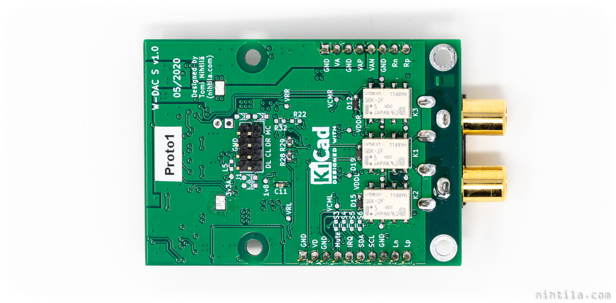
PCB
Form factor is the same as W-DAC with 70 x 50 mm 4-layer PCB. Relays are placed on bottom side as they could never fit on top, and here they are also close to the signals keeping routing short.
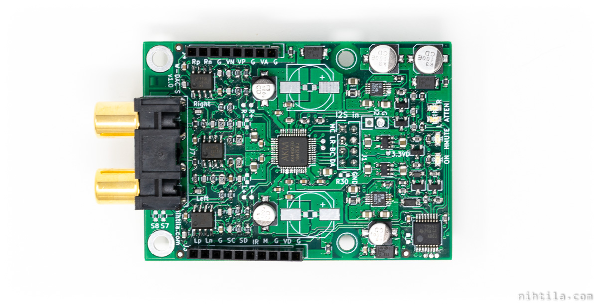
Why green PCB now? Well, JLCPCB had/have so good discounts for some stackup/colour combinations that red PCB would have cost four times more! At least they are easy to distinguish from their non-I2C counterparts. And it looks almost exotic after using all other colours for so long!
I2C control
I do not provide control software. If you buy a board, you need to take care of this. However, if you have ever done anything similar, it is a rather straightforward task. Here are some tips to get started.
Your best friend here is AK4493EQ datasheet and TCA9554 datasheet to see how to set up the DAC and I/O expander, respectively. But in order to get started, I have listed here a few lines of writes that give you audio out. I may write another post diving deeper in the settings available inside the DAC.
First of all, note the I2C addresses. These are defaults and can be changed with resistors R22, R23, R32, and R33; the resistors control the two least significant address bits of both ICs.
- AK4493: 0x12
- TCA9554: 0x22
Also remember that I2C bus needs pull-up resistors. If your host side doesn’t have them, populate R28 and R29; value is not strict.
I have used here syntax Write(I2C address, register address, data). In fact, I use Analog Discovery 2 when testing devices with I2C and that’s how it is written there as well.
TCA9554 setup
Below is a simple setup for TCA9554.
// Following lines power up DAC and set attenuation relays off.
// All pins are input at startup.
Write(0x22, 0x03, 0x8F); // set ATTEN_L, ATTEN_R, and PDN outputs, the rest inputs
Write(0x22, 0x01, 0x40); // set PDN bit high to power up DAC
In this example Mute is not controlled by TCA9554 but come outside from host or W-Input S. You can also control mute with TCA9554 by setting the pin as output.
TCA9554 also has IRQ for input pins but it’s not needed in W-DAC S. You could try to read sample rate using LRCK signal going to P7 of TCA9554 but it may be too fast to get sensible reading. I have not tried this.
Update 23/1/2021:
When attenuation relay is switched, it may cause very nasty glitch. Somehow this wasn’t a bad issue when initially testing the board but now when building my own preamp, it caused awful glitch. Luckily the solution is simple – mute output while switching the attenuation relay. These small relays are quite fast and switch in around 2ms. Therefore, the suggested flow and what I have done in my own preamp is:
- Turn output mute relay on
- Wait 5 ms
- Toggle attenuation relay
- Wait 5 ms
- Disable output mute
This gets rid of the glitch and you only have a brief switch and break of only 10 ms.
AK4493 setup
Write(0x12, 0x00, 0x87); // set auto clock mode and 32-bit I2S interfaceThat’s really all you need to get I2S audio out! You can change volume with registers 0x03 and 0x04. In addition, you can find bits for changing the digital filter, de-emphasis filter, invert or soft-mute outputs, configure the DAC for DSD, and so on. You can even set the DAC for mono operation to further improve SNR; I have not evaluated this though.
Measurements
As usual, the specs are not guaranteed but typical. That being said, significant deviations are not expected which can be said after measuring around two dozens of W-DAC 4493s for some sort of statistics.
Measurements have been carried out using Audio Precision APx555 audio analyser. Unless otherwise mentioned, measurement bandwidth is 20 kHz and frequency in single-tone measurements is 997 Hz.
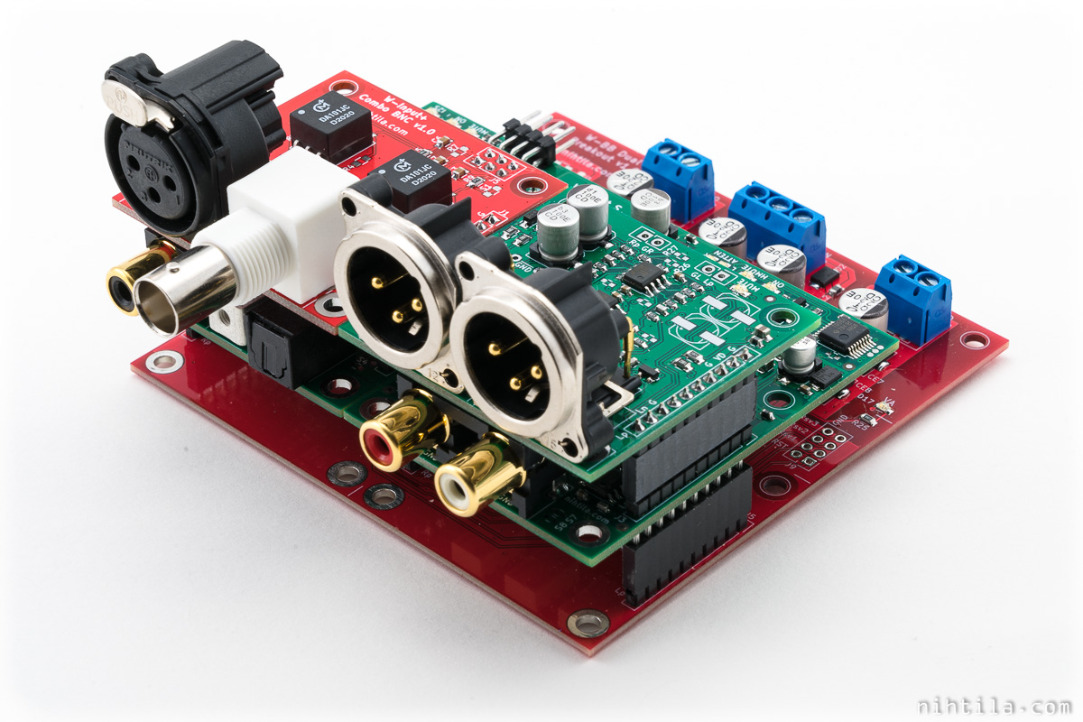
W-DAC is powered by a W-BB Dual PSU connected to bench power supply. Default filter Short Delay Sharp was selected in AK4493. I have written about these filters before.
Power consumption
Required supplies and rough current consumption are as follows:
- VAP: +15 V, 79 mA
- VAN: -15 VA, 32 mA
- VD: 5 V, 75 mA (when all relays are on; relays take around 20 mA each)
±15 VA are used for opamps so it’s not very strict. I wouldn’t go higher due to excess power consumption but it can be a bit lower.
VD cannot be higher than 5.5 V.
Full volume, 0 dB
Measurements results at full volume are practically identical to W-DAC 4493 so I just repeat the numbers here without all graphs. Here the focus is on differences so mainly what happens when we adjust volume, and especially comparing between pure digital volume and hybrid volume using the relays.
Output level
Maximum output, 0 dBFS level is 2 Vrms / 6 dBV.
Output stage is DC coupled so there are no capacitors on signal path. Therefore, there can be a small DC level at the output. Typical DC offset is less than 2 mV.
Dynamic Range / SNR
Unweighted SNR is 119 dB and A-weighted SNR 121 dB. A-weighted dynamic range is the same 121 dB.
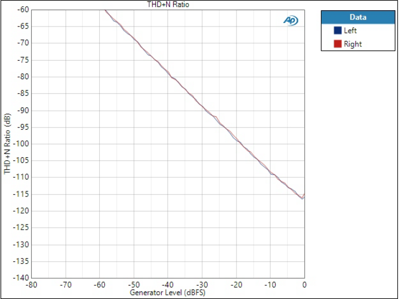
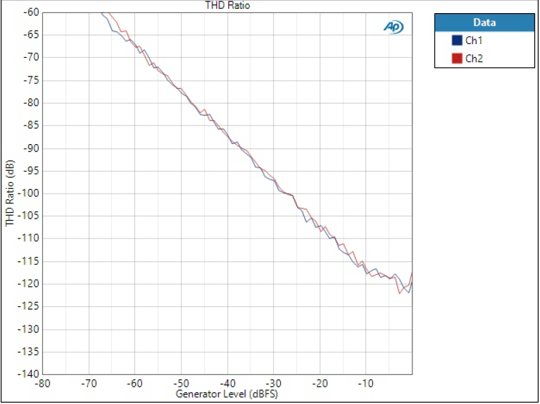
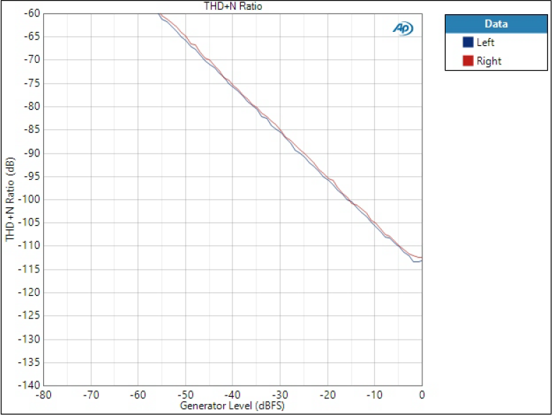
THD+N and THD
THD+N ratio curve improves almost all the way until 0 dBFS; there is a small knee at -1 dBFS. Thus, typically THD+N peaks at around -1 dBFS. In THD there is more variation due to very small level, and it shows sharper knee. Thus, -2 dBFS is given here.
THD+N, 997 Hz
- THD+N, -1 dBFS: -115 dB
- THD, -2 dBFS: -121 dB
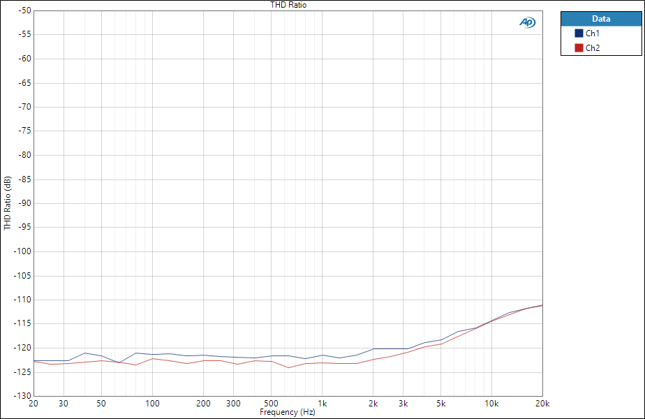
There is also one THD vs. frequency plot in 90 kHz bandwidth below.
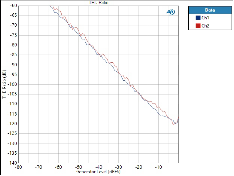
Volume decreased -8 dB digitally
Ok so what happens when we adjust the volume in the DAC chip, in this case to -8 dB? It’s basically the same as having the volume at 0 dB but input tone at -8 dBFS; so -8 dBFS at above THD vs. Amplitude graphs becomes 0 dBFS. Key figures below:
- SNR: 111 dB (113 dBA)
- THD+N, -1 dBFS: -109 dB
- THD, -2 dBFS: -117 dB
Most importantly, noise level remains the same -113 dBV as in 0 dB volume case. As signal level is 8 dB lower, SNR/DR drops 8 dB. The same happens to THD+N at lower levels where noise dominates. At 0 dBFS the difference is not as big as the output stage inside the DAC distorts less with smaller signal (I presume). Graphs below.
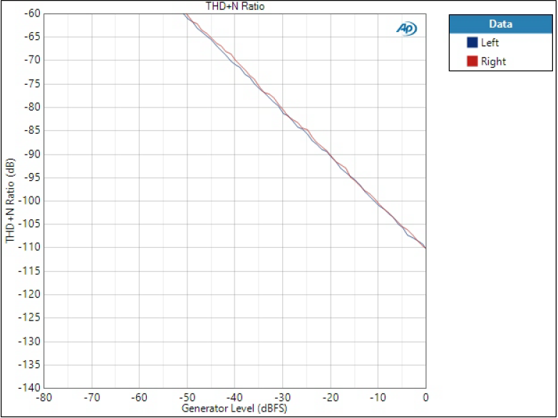
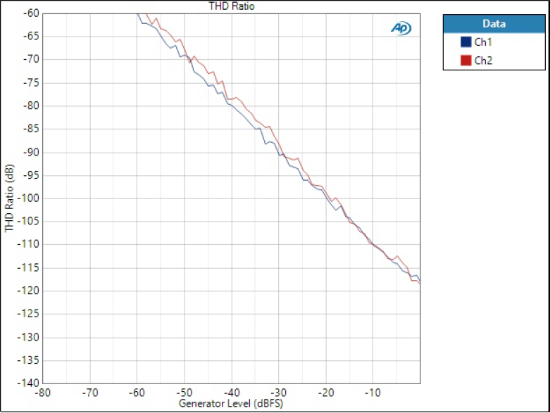
Volume decreased -8 dB with relay
Now volume is set to -8 dB by using the relay attenuation, and digital volume is at 0 dB.
- SNR: 116 dB (118 dBA)
- THD+N, -1 dBFS: -113 dB
- THD, -2 dBFS: -119 dB
So we have gained a good few dB in every key parameter compared to software volume. This is due to noise being pushed to -117..-118 level with the analog attenuation.
Other volume settings
As relay attenuation is fixed to 8 dB, volume settings from -7 dB to 0 dB are digital, and settings below -8 dB are a combination of analog and digital. And it’s this latter range where we gain the benefit, and that’s the range where we are basically always when listening to music. Therefore, this is a real practical improvement.
Advanced tip for volume control programming
One thing we notice when comparing the -8 dB SW and HW graphs – the knee near maximum level; digital attenuation doesn’t have it but relay attenuation does. In -8 dB relay attenuation we are driving the DAC output at full 0 dB level where it starts distorting slightly. If you really want to take one step further in optimising this hybrid scheme, you could avoid these -1 dB and 0 dB steps when the relay is used. You could program the control something like this:
- 0 dB: 0 dB digital (slight increase in THD)
- -1 dB: -1 dB digital (slight increase in THD)
- …all digital
- -8 dB: -8 dB digital
- -9 dB: -9 dB digital
- -10 dB: -2 dB digital, -8 dB analog (no increase in THD as we don’t drive output at full 0 dB)
- -11 dB: -3 dB digital, -8 dB analog
and so on. This way you would not introduce the knee again at -8 dB when digital volume goes back to 0 dB. Not maybe any practical meaning but just an idea if you really want to optimise this – and it comes for free!
Files
References and additional information
- 2-page factsheet
- AK4493EQ product page (you need to sign up to get datasheet)
- TCA9554 datasheet
- Wee DAC system
- W-DAC 4493
- W-Input S
- DAC digital filters part 2 – deeper dive into AK4490 and AK4493 filters
- DAC digital filters and their impact in time and frequency domain
- Understanding audio measurements: THD+N vs. amplitude and frequency
- Understanding audio measurements: noise, SNR, and dynamic range
Version history
Schematics / PCB version history and known errors and bugs
- v1.0B Initial version
- Silk screen for ‘MUTE’ is confusing. ‘MUTE’ LED is on when the relay is on, meaning mute is off. Will change silk screen text to ‘UNMUTE’ or so in next revision.
- As mentioned above, attenuation relay slightly changes filter characteristics. No practical meaning but could have done differently.
This page version history
- 28.12.2020 Initial version
- 23.1.2021 Added note of glitch and suggested solution regarding attenuation relay toggle
Buy boards here.
1 comment
[…] the analog stuff. I got two ADC AK5572 to be able to support four input mono channels and three W-DAC S 4493 to support three stereo output channels. For one of the output channels I got a W-Output XLR Mute […]
Comments are closed.