
Wee DAC is a flexible modular system and there are several different baseboards for different configurations depending on the system requirements:
- DAC with S/PDIF inputs or only I2S-input
- Two channel DAC or four channel (2x stereo) I2S DAC
- Number of S/PDIF inputs
- Vertical or horizontal stack of boards
Configuration options
There are four different boards and larger dual boards can be configured in two different ways.
With flexibility comes also complexity so the number of options may be overwhelming. Following photos show examples of different configurations. And always feel free to ask if you’re unsure what board you need.
Let’s first have a look at the narrower boards, called vertical stack here.
Vertical stack
These boards are
- W-BB Breakout
- W-BB PSU
Breakout board just breaks out power supply connections to screw terminals and provides a bit of extra capacitance and very simple protection. Thus, all four supplies (5 VD, 7.2 VA, +15 V, -15 V) must be provided externally.
W-BB PSU has voltage regulators for all four supplies on board and only requires dual input of ±18 V or similar to operate.
These boards can be used for
- W-DAC (and optional W-Output XLR addon)
- W-Input (and optional W-Input+ addon)
- W-Input and W-DAC (and optional W-Output XLR addon)
See examples below.
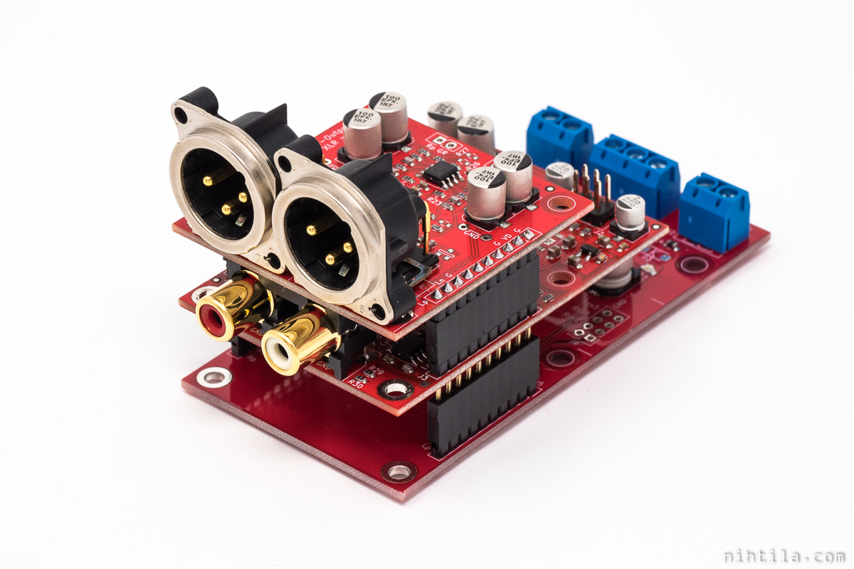
W-BB Breakout and W-DAC with W-Output XLR
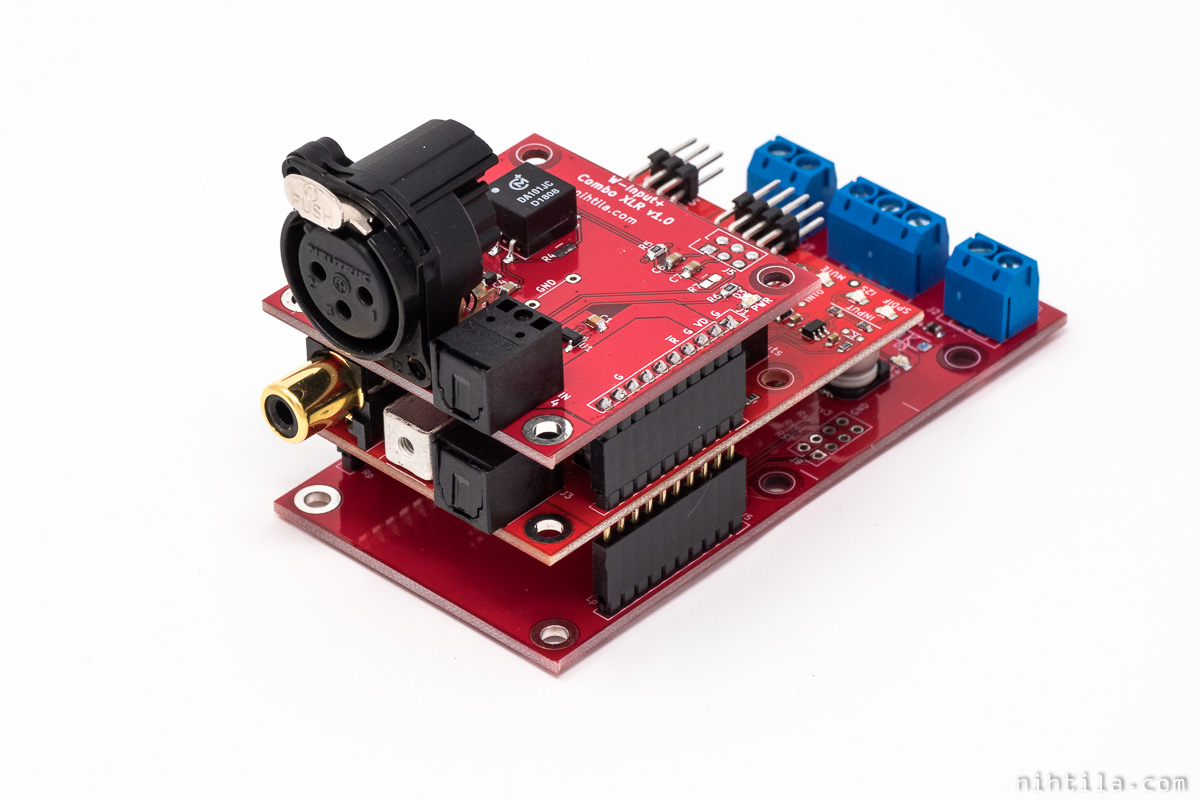
W-BB Breakout and W-Input with W-Input+ Combo XLR
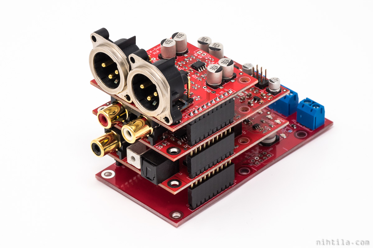
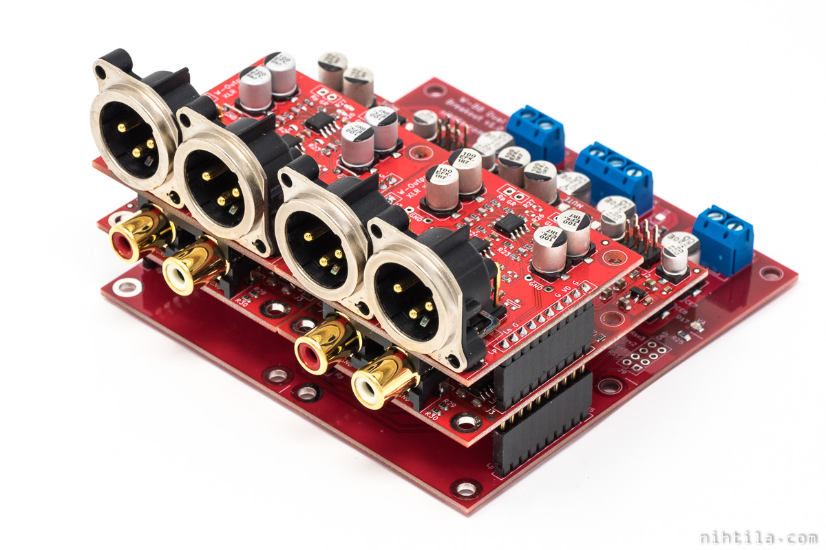
W-BB Breakout, W-Input, and W-DAC with W-Output XLR
Downside of the last option is height. For lower stack, larger baseboards can be chosen for horizontal stack.
Horizontal stack
Similarly, there is a breakout board and a PSU board available:
- W-BB Dual Breakout
- W-BB Dual PSU
In these boards W-Input and W-DAC can be mounted next to one another, making the stack lower. Moreover, it is possible to use both W-Input+ addon and W-Output XLR at the same time.
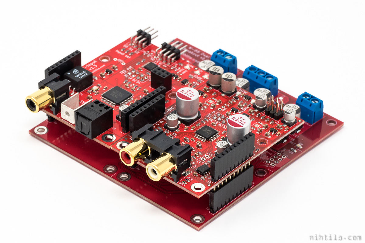
W-BB Dual Breakout, W-Input, and W-DAC

W-BB Dual Breakout, W-Input with W-Input+ Combo XLR, and W-DAC with W-Output XLR
4-channel I2S DAC
Things get a bit more complicated as I wanted to make support for two W-DACs for 4-channel setup. This is with I2S input only though, no W-Input can be used in this configuration.
W-BB Dual Breakout and 2x W-DAC with W-Output XLRs
No baseboard at all?
Baseboard is not needed to use W-Input or W-DAC, you can always just wire supplies to the edge connectors if you want to save space or money. This may be useful if enclosure height is limited as baseboard always adds height. W-Input and W-DAC boards have screw holes so baseboards are not needed for mechanical reasons either.
Just make sure wiring is correct as there is no protection on overvoltage or reverse voltage on W-Input and W-DAC!
Design
Here are schematics and brief design description of all baseboards. Basically the idea is as follows:
- Breakout boards only route supplies to screw terminals and provide a bit of capacitance, LEDs and very basic protection
- PSU boards provide voltage regulators for all supplies
Voltage protection
Supply protection here is very basic, just TVS on supply lines. TVS works like a zener diode, limiting the voltage across it. However, as other diodes, it cannot offer very steep transition from working voltage to breakdown. For example, SMA4F5A TVS used here has specified working voltage is 5 V but it breaks down at around 6.7 V. That may be enough to damage 5 V circuits. Therefore, take care to avoid overvoltage. But if it happens, TVS can limit it to at least a more reasonable value.
TVS also works as reverse voltage protection for a circuit after it – but not to a circuit supplying it. In reverse voltage condition, TVS shorts the supply which may cause damage to the external power supply.
TVSs used here are small so they cannot withstand heavy loading condition for a long period of time. It is always highly recommended to use fuses somewhere in the power supply.
W-BB Breakout
Very simple breakout board to route supplies to screw terminals (or optionally to pinheaders).
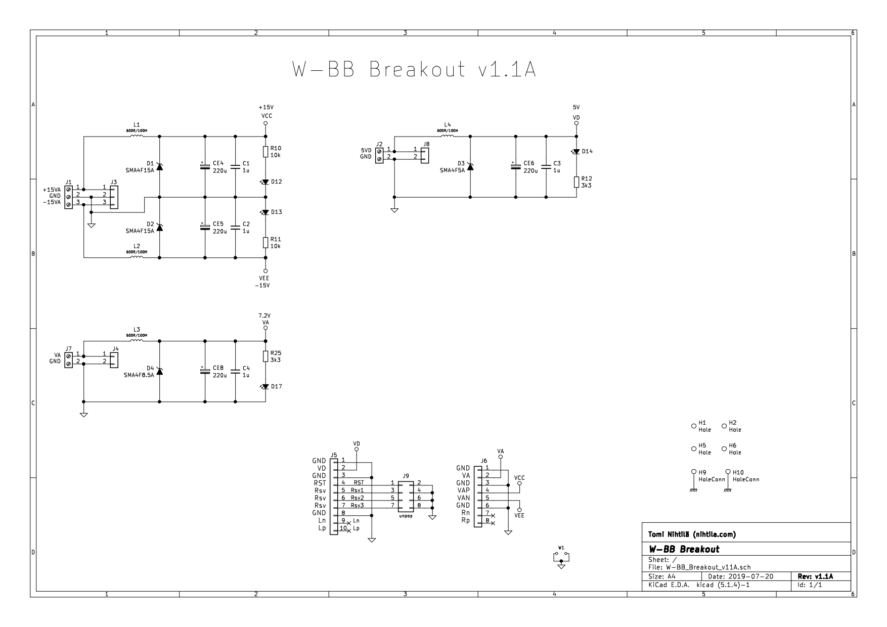
W-BB Breakout
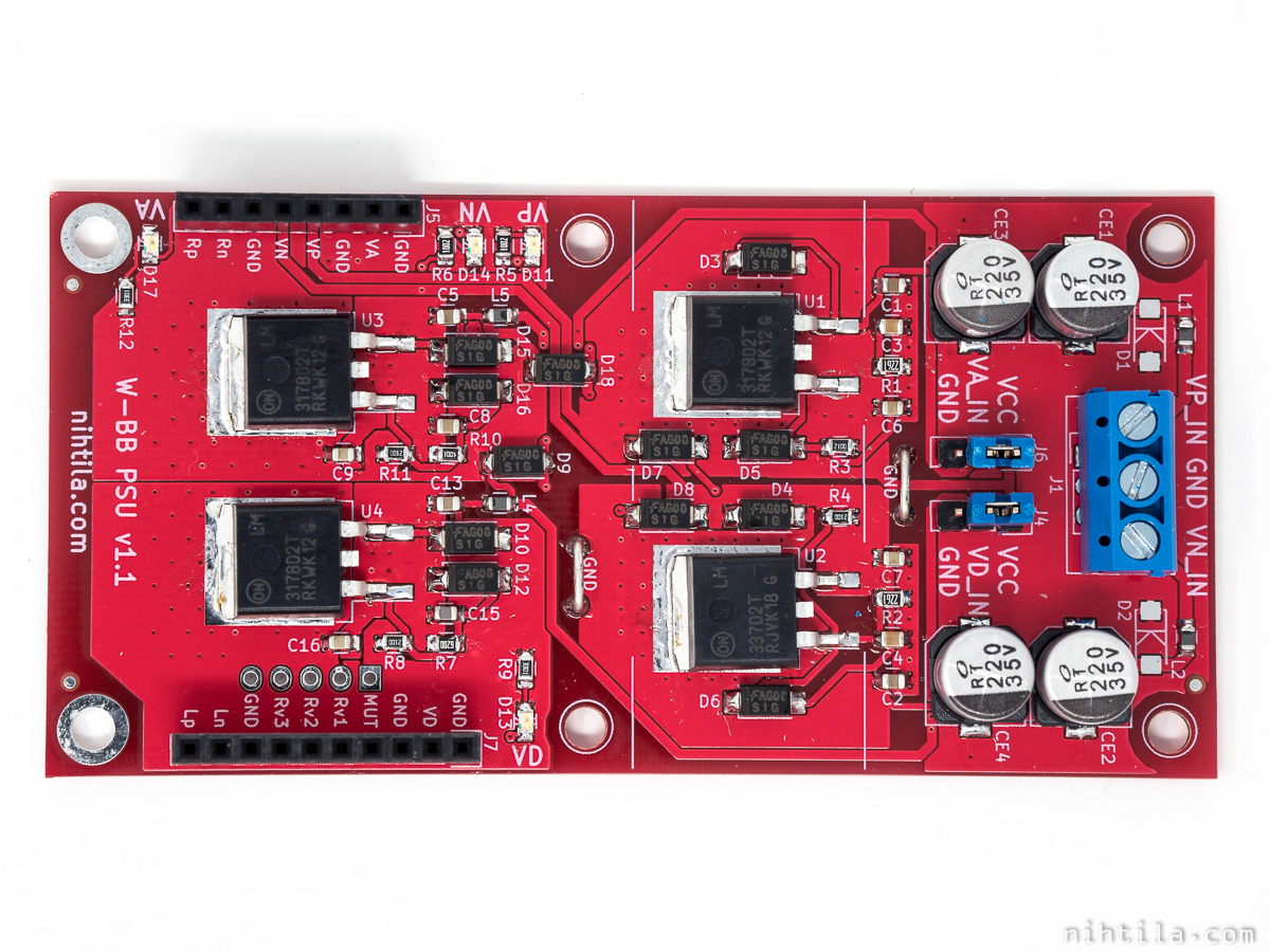
W-BB PSU
Power supplies are basic circuits using robust LM317/LM337 regulators. These are in D2PAK-3 case soldered directly on board.
Maximum input voltage to ±15 V circuit here is ±30 V and to VD and VA circuits +15 V. Please note that using high voltages may overheat regulators and board if load is high.
Default configuration is to supply VA and VD regulators from +15 V VCC supply. In this case the whole board just needs a dual supply of around ±20-25 V However, these can be taken elsewhere, for example from separate transformer, by removing jumper links and using those pinheaders as input.
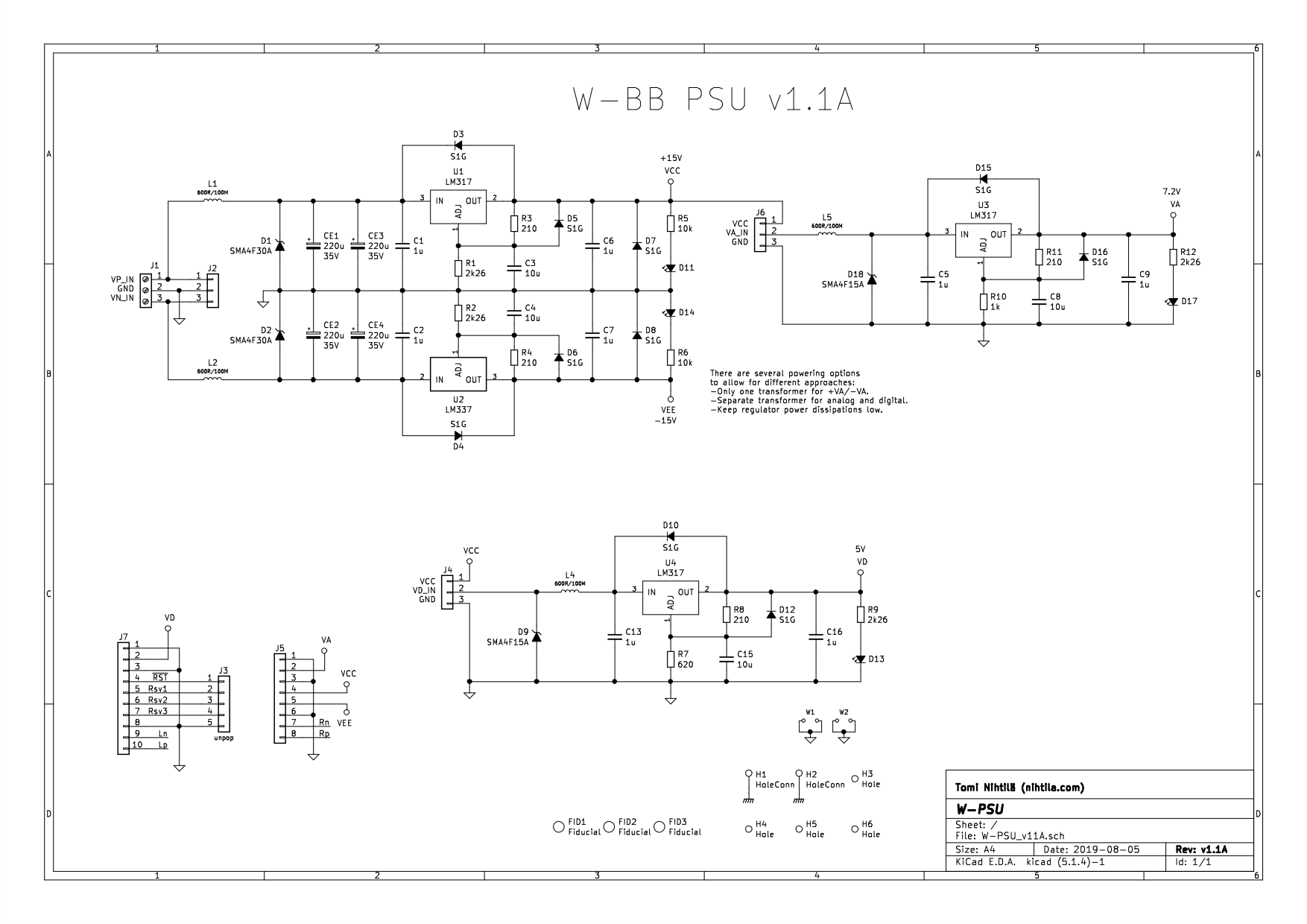
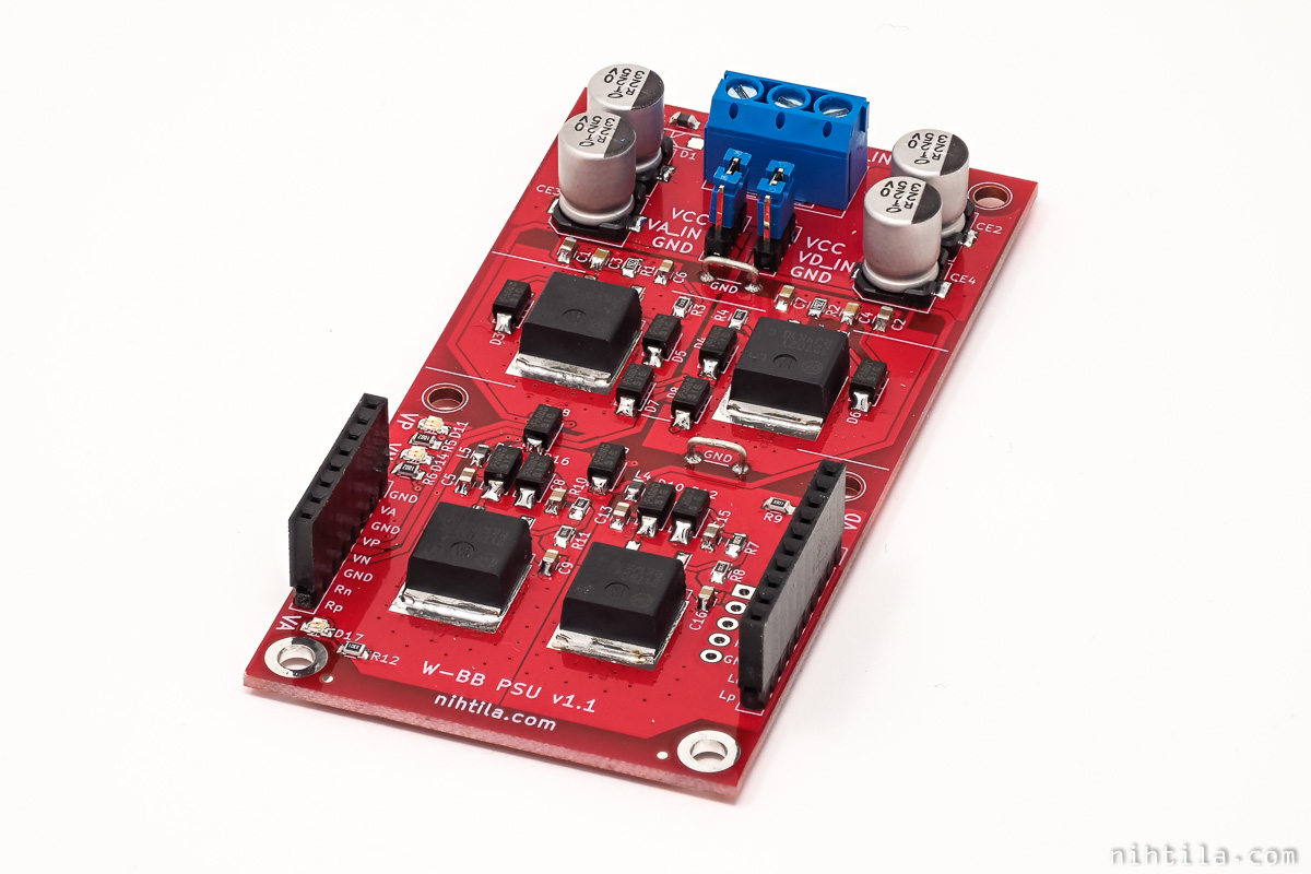
W-BB PSU
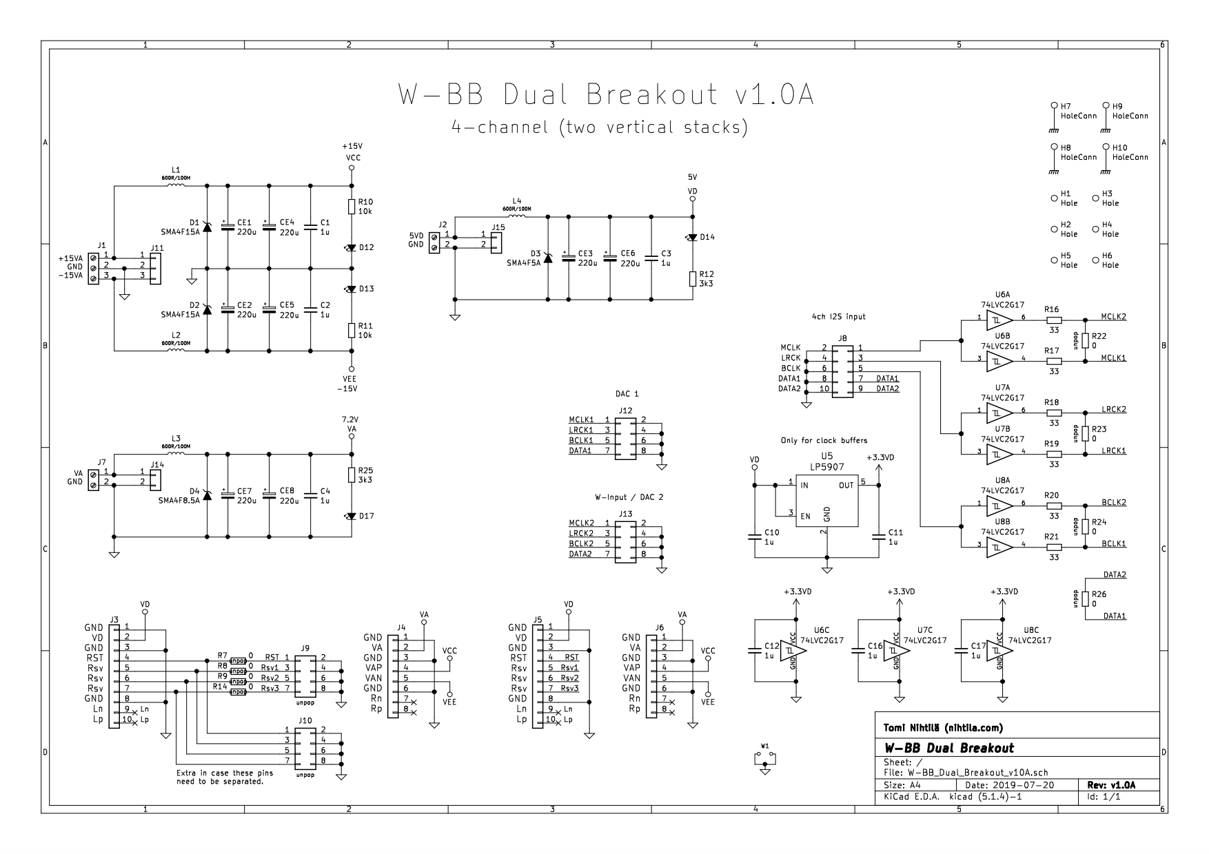
W-BB Dual Breakout
Dual slot version of breakout board. Two population options make it slightly more complicated.
There are two population options where A-version is for 4-channel dual-DAC setup, and B-channel is for 2-channel W-Input and W-DAC setup.
- In stereo B-version I2S signals are routed directly from W-Input slot to W-DAC slot.
- In 4-channel A-version external I2S is brought to J8 where all clocks are split and buffered to each slot, and data signals taken separately. In this case W-Input cannot be used; it’s just 4-channel I2S to two stereo DACs.
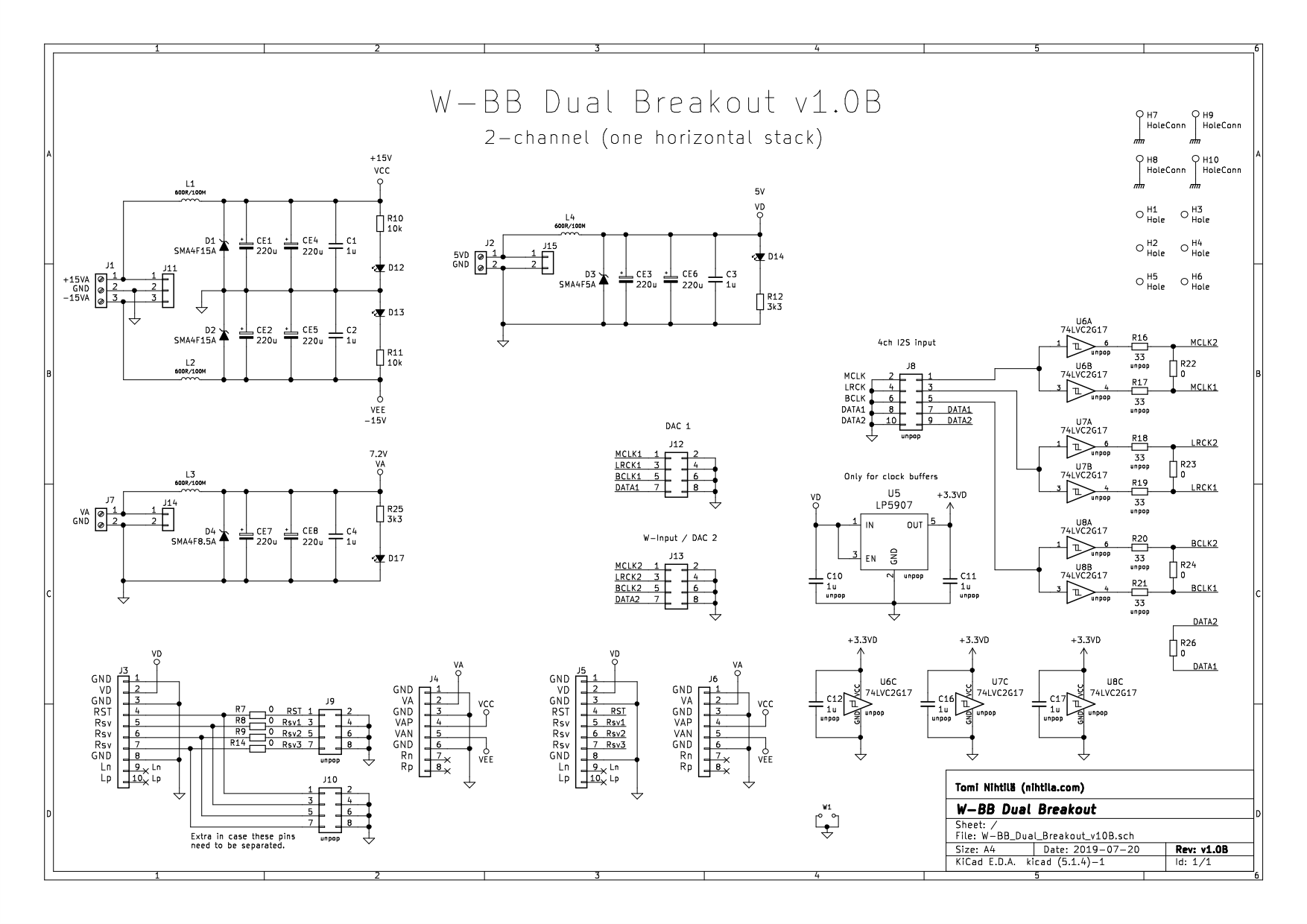
W-BB Dual Breakout B-version (2-channel)
W-BB Dual Breakout A-version (4-channel)
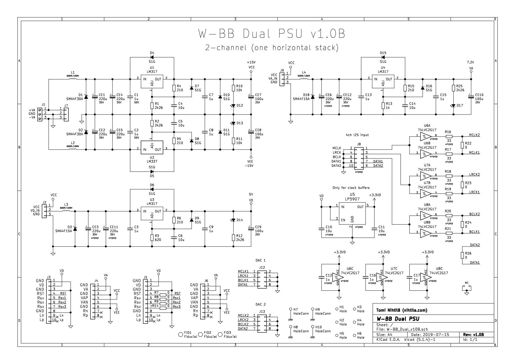
W-BB Dual PSU
Power supply version of dual board baseboard.
As in Dual Breakout board, there are two population options where A-version is for 4-channel dual-DAC setup, and B-channel is for W-Input and W-DAC setup.
- In stereo B-version I2S signals are routed directly from W-Input slot to W-DAC slot.
- In 4-channel A-version external I2S is brought to J8 where all clocks are split and buffered to each slot, and data signals taken separately. In this case W-Input cannot be used; it’s just 4-channel I2S to two stereo DACs.
Otherwise power supply circuits are very basic using robust LM317/LM337 regulators. These are in D2PAK-3 case soldered directly on board.
Maximum input voltage to ±15 V circuit here is ±30 V and to VD and VA circuits +15 V. Please note that using high voltages may overheat regulators and board if load is high.
Default configuration is to supply VA and VD regulators from +15 V VCC supply. In this case the whole board just needs a dual supply around ±20-25 V However, these can be taken elsewhere, for example from separate transformer, by removing jumper links and using those pinheaders as input.

W-BB Dual PSU (2-channel B-version)
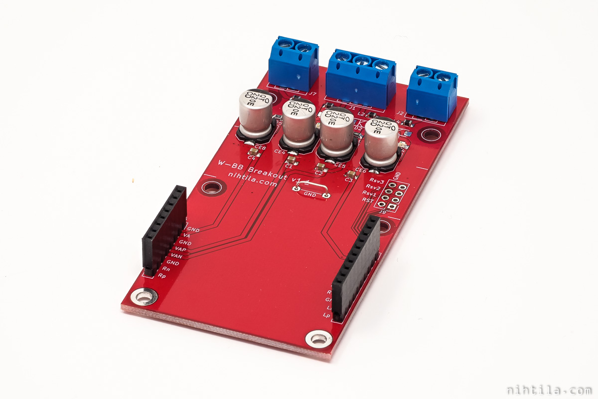
PCB
PCBs are 100 mm x 50 mm 2-layer boards for the narrow versions and 100 mm x 100 mm 2-layer boards for the dual versions.
Schematics and layout have been done with KiCad and components sourced from Mouser and Digikey. PCBs are from Elecrow.
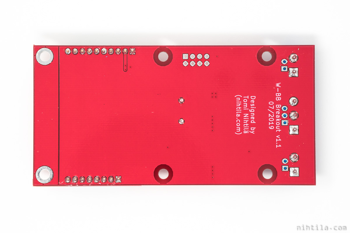
W-BB Breakout
W-BB PSU

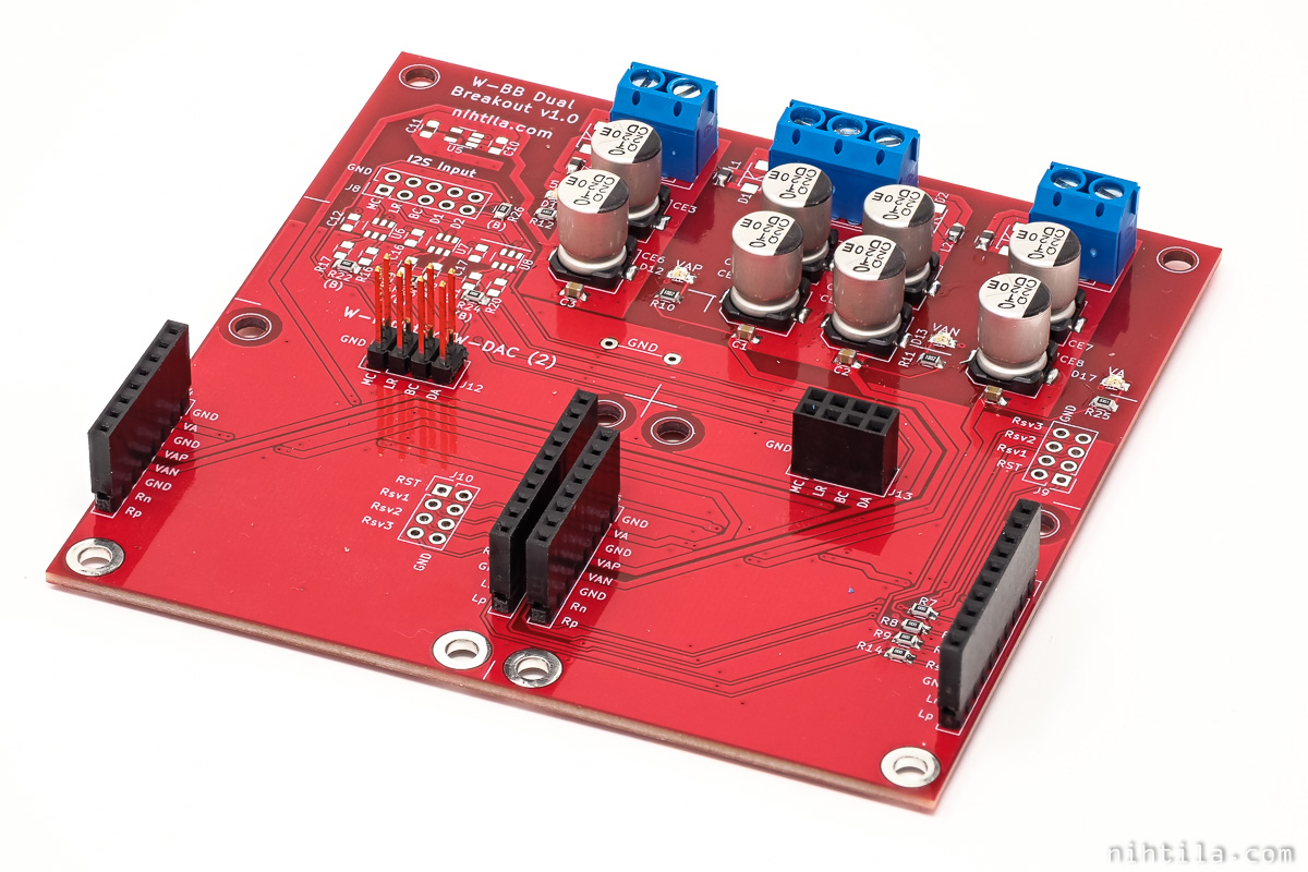
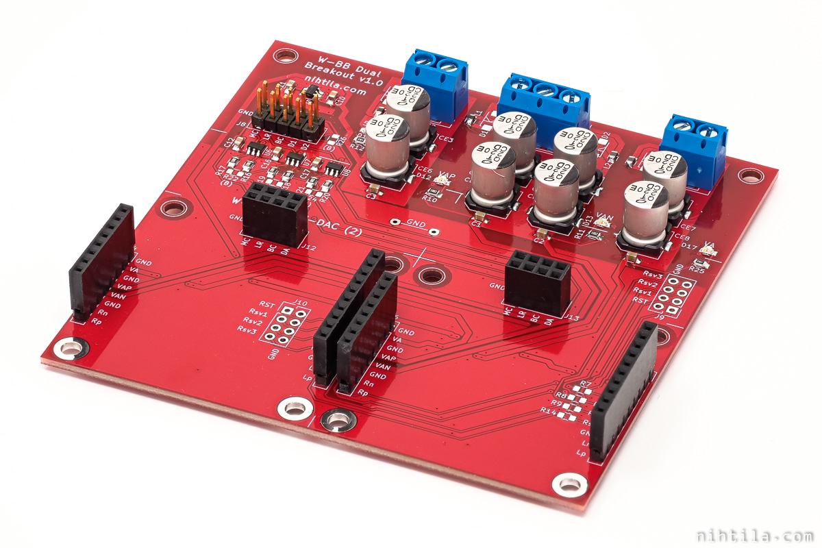
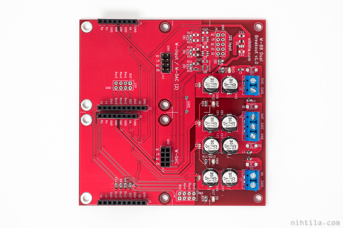
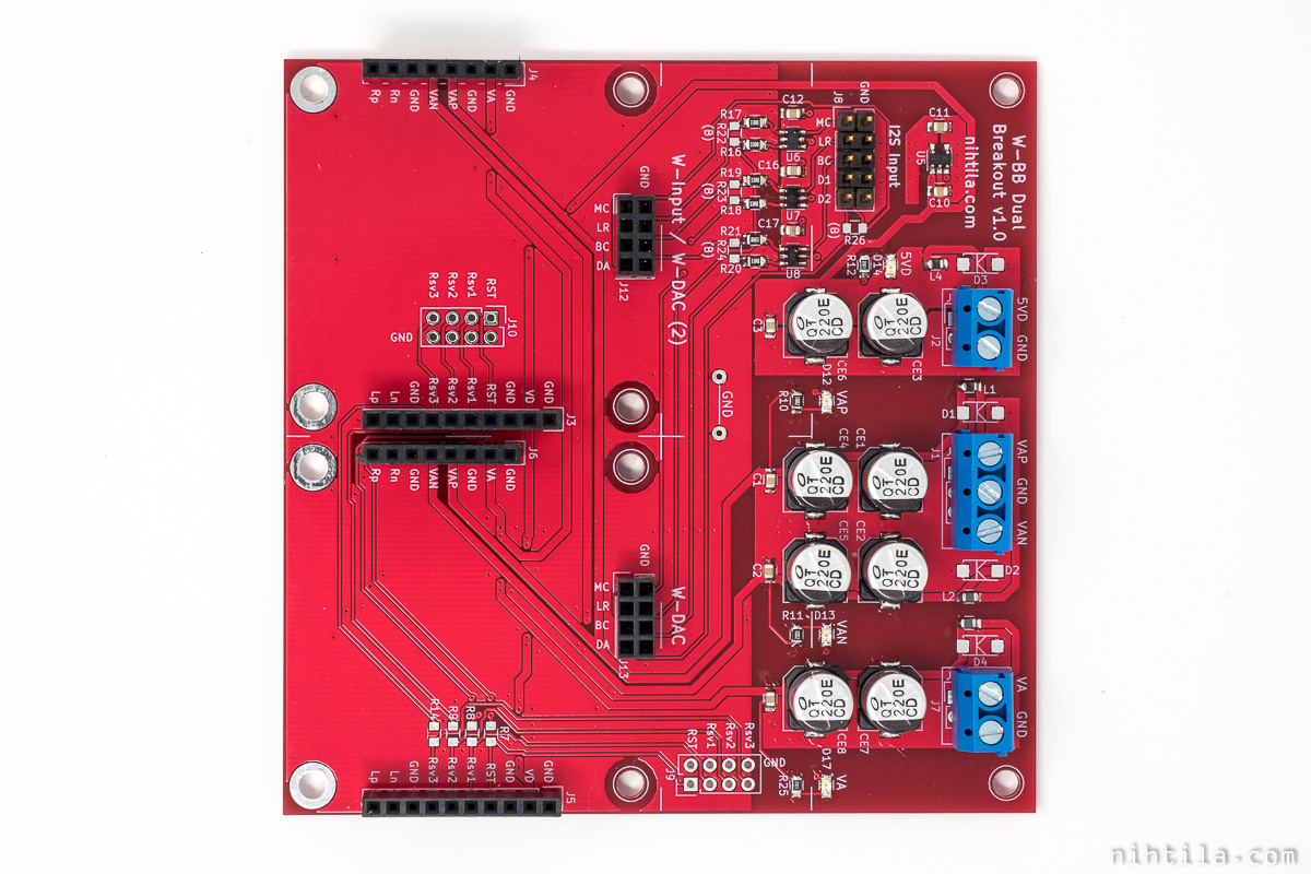
W-BB Dual Breakout
Here the difference between 4-channel A-version and 2-channel B-version are shown. 4-channel version has female pinheader socket in both slots and clock buffers populated along with additional pinheader on top right corner in photos below. 2-channel version does not have buffers populated and one slot has male pinheader for W-Input.
W-BB Dual Breakout B (2-channel version) top
W-BB Dual Breakout A (4-channel version) top
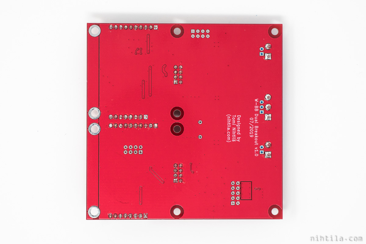
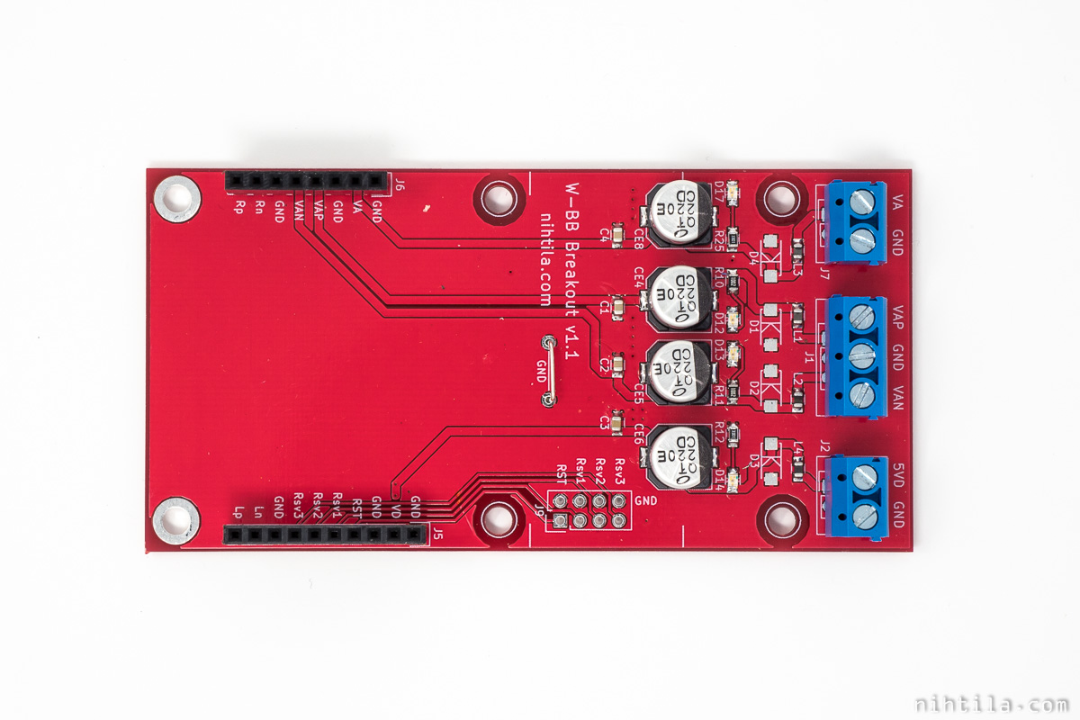
W-BB Dual Breakout bottom
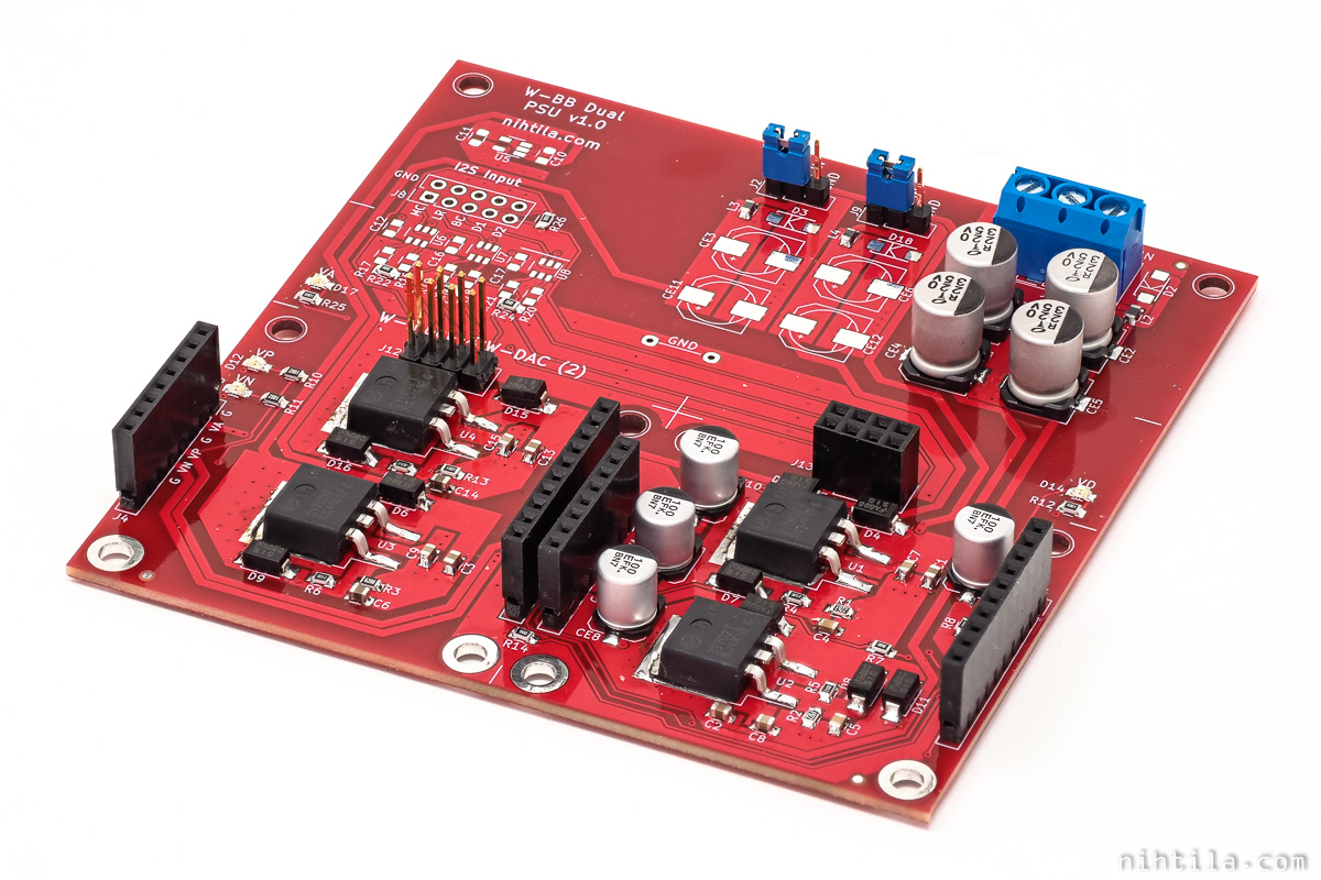
W-BB Dual PSU
Here only 2-channel B-version is shown, but A-version has similar differences to W-BB Dual Breakout shown above.
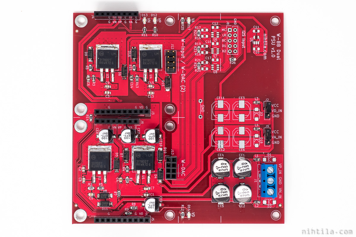
W-BB Dual PSU B (2-channel version) top
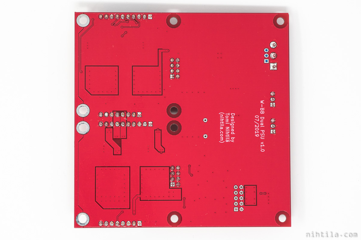
W-BB Dual PSU bottom
Measurements
W-DAC performance measurements have been done using W-BB Dual PSU board. No actual power supply measurements have been done on PSU boards but these are very simple regulator circuits and should follow regulator characteristics.
Note that output voltages may not be very accurate (especially negative -15 V) but this is not critical.
In addition, simple signal integrity checks were done on buffered clocks on 4-channel version of Dual boards.
Current consumption
Breakout boards consume around 1 mA extra per supply due to LEDs.
PSU boards take more extra current, following example is with ±18 V supply:
- +18 V: 23 mA
- -18 V: 7 mA
Examples of full system current consumption using W-BB Dual PSU:
W-BB Dual PSU with W-Input and W-DAC:
- +18 V: 115 mA
- -18 V: 38 mA
W-BB Dual PSU with W-Input and W-Input+ Combo, and W-DAC and W-Output XLR (the most complete system)
- +18 V: 147 mA
- -18 V: 60 mA
Files
Schematics are shown above and reference designators are on silkscreen, thus only BOMs are listed here.
- W-BB Breakout v1.1A BOM
- W-BB PSU v1.1A BOM
- W-BB Dual Breakout v1.0A BOM
- W-BB Dual Breakout v1.0B BOM
- W-BB Dual PSU v1.0A BOM
- W-BB Dual PSU v1.0B BOM
References and additional information
Version history
Schematics / PCB version history and known errors and bugs
W-BB Breakout
- v1.1A First released version
W-BB PSU
- v1.1A First released version
W-BB Dual Breakout
- v1.0A First released version
W-BB Dual PSU
- v1.0A First released version
This page version history
- 5.11.2019 Initial version
If you have more questions about these boards or which one to choose, please comment below or send an email.
Buy boards here.
3 comments
Gotta spend the proper time looking through the final version of the Wee DAC when I eventually find the time but after a quick view it seems awesome! Great job!
Thanks! It became a bit complicated indeed, should have limited the options a bit more but it just often happens I want to try everything. I listed the boards on Tindie and tried to keep the pages there a bit simpler and less technical so may be easier to start from there.
Well this is mostly a hobby thing right? So I think you did the right thing on doing what you wanted instead of what’s the most “commercial”!
Comments are closed.