
Two examples of USB to I2S boards have been tested with W-DAC. They both have very extensive but also different feature sets. Key takeaways from measurements are:
- Both can get the best performance out of W-DAC 4493: -115 dB THD+N and 121 dBA dynamic range
- Lack of galvanic isolation in MCHStreamer may become problematic though and deteriorate performance figures
Wee DAC system does not have its own USB to I2S module but any compatible module can be used to provide USB input. If only USB input is needed, such module can be connected directly to W-DAC’s I2S input. If S/PDIF inputs are also needed, W-Input provides extra I2S pass-through for USB to I2S module.
Introduction
By saying ‘compatible’ USB module, what is compatible then? Basically almost any module should be compatible but as I2S is not a plug and play connection and we cannot try all options, it is up to the user to check they work together. There are certain things to check:
- Logic level must be 3.3 V.
- Sample rate must within supported range which is very wide with W-DAC, up to 768 kHz.
- Bit Clock, may get trickier to find what it is but luckily these DACs are flexible. Usually Bit Clock is 64x sample rate, meaning there are 32 bits per channel (even if data is 16 or 24 bits).
- Master Clock, MCLK, may also be trickier to know exactly how it behaves. Again, luckily DACs are flexible; it may affect performance though. It is common to have MCLK fixed and oversampling ratio changes when sample rate goes up.
- For example, at 48 kHz MCLK may be 24.576 MHz which is 512 times the sample rate.
- Going to 96 kHz MCLK does not double but remain the same 24.576 MHz; ratio is now 256 instead. Note that Bit Clock does double when sample rate doubles.
- This MCLK/Fs ratio gets smaller when sample rate goes up.
- The situation is the same for 44.1 kHz family of sample rates except MCLK is 22.5792 MHz
Above is approximately how S/PDIF receiver in W-Input and many USB to I2S modules work. Even if not, W-DAC likely works just fine. Overall, when MCLK/Fs ratio gets smaller, performance may deteriorate slightly; it depends on DAC ICs.
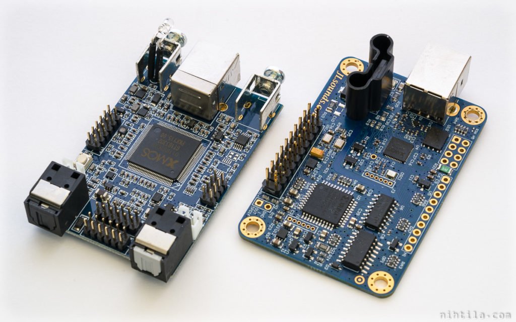
Anyway, as two examples of USB to I2S modules I have taken two boards I have: JLSounds I2SoverUSB and miniDSP MCHStreamer. They both have very extensive but also very different feature set so please check their websites for more information. Here is a summary of features:
JLSounds I2SoverUSB
- Stereo output, PCM or DSD
- PCM sample rate up to 768 kHz, resolution up to 32 bits
- DSD over PCM up to DSD256, DSD Native up to DSD512
- Directly supports numerous DACs
- Galvanic isolation
- Possibility for external MCLK
- ASIO drivers
See more information on JLSounds website.
miniDSP MCHStreamer
- Up to 12 output channels, up to 12 input channels
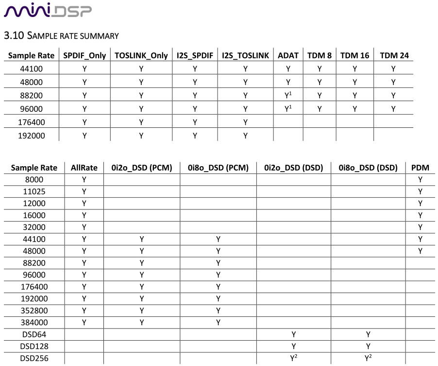
- Supports range of formats: PCM, DSD, PDM, TDM, S/PDIF, Toslink, ADAT
- Not all channels, sample rates, and formats/interfaces are supported simultaneously
- PCM up to 8 channels in/out, sample rate up to 384 kHz, resolution up to 32 bits
- DSD up to 8 channels DSD256
- ASIO drivers
See more information on miniDSP website.
Differences between the two
Both boards have extensive feature set and lots of differences. See datasheets for detailed features but some of the main differences regarding our use case with W-DAC are listed here:
- Only I2SoverUSB has galvanic isolation
- MCHStreamer supports I2S input and output which is rather rare, I2SoverUSB is only playback device as most USB-I2S boards
- I2SoverUSB supports up to 768 kHz sample rate, MCHStreamer up to 384 kHz
- MCHStreamer can support up to 10 I2S channels, while I2SoverUSB is stereo
- Note that although MCHStreamer has an impressive list of support for multiple channels, formats, and interfaces, these cannot be used simultaneously. There are NINE different firmware versions so you basically need to choose what format to use. Some firmwares support several formats but there are limitations in channel count and sample rate. So check the user manual before buying. For example, the firmware used here supports only I2S but with 10 channels in and out and sample rate up to 384 kHz.
- I2SoverUSB supports external MCLK but MCHStreamer MCLK is always output
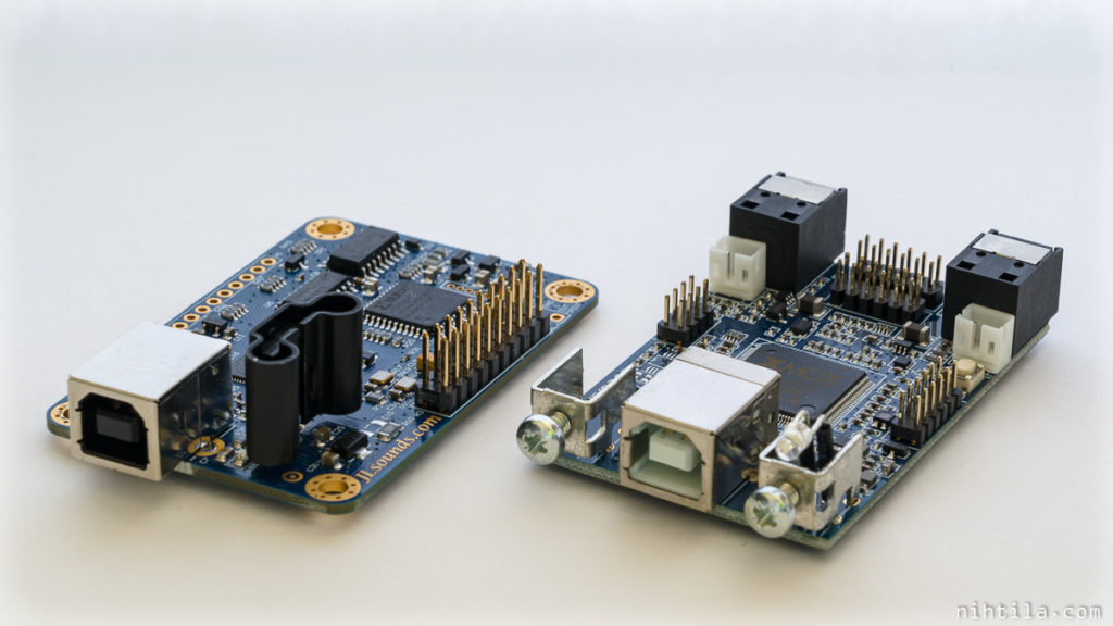
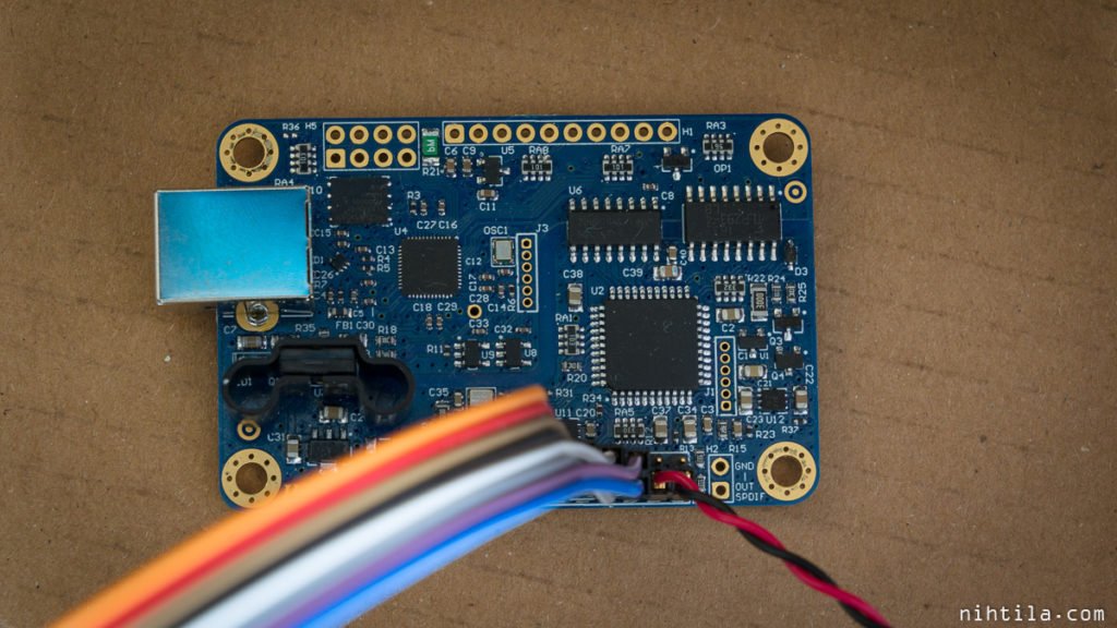
MCHStreamer uses smaller pinheaders instead of more common 0.1″ headers. Two wire sets are included with the board. Unfortunately this board suffers from the same issue that has been in basically all miniDSP boards I have used – lack of ground connections. There is a 12-pin header with all I2S signals and ONE ground pin! Fail. So a better option than using their provided wire set would be to make your own custom cable with every second pin ground.
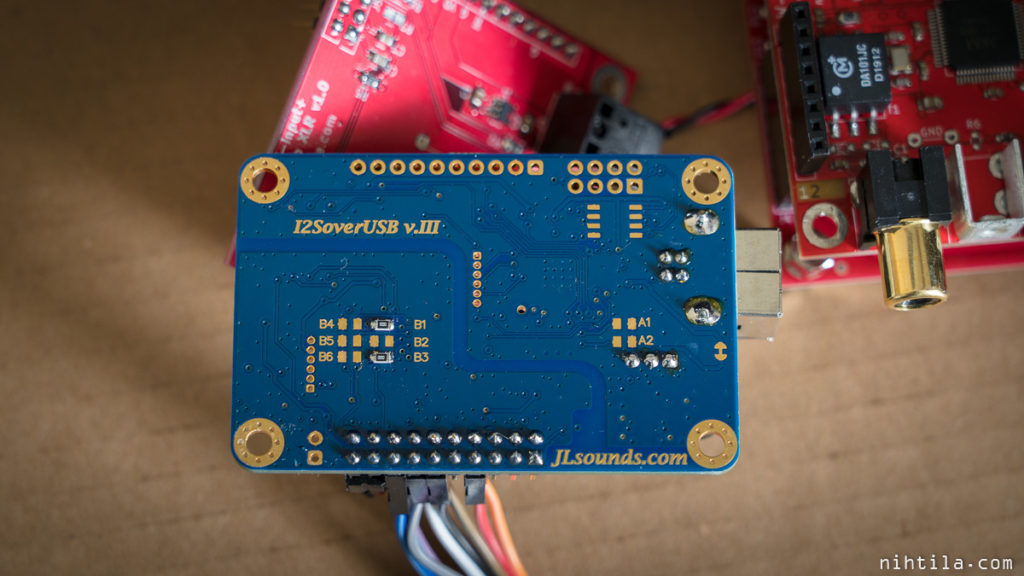
We can see that I2SoverUSB have two oscillators onboard, also mentioned on their website. One for 44.1k family of sample rates and another for 48k family. I don’t see any oscillator on MCHStreamer, meaning they probably use an internal clock or USB clock and a PLL for all clocks.
This leads to rather different clocking scheme that could potentially lead to performance differences. I2SoverUSB performs reclocking using crystal oscillators after the galvanic isolation barrier. This should improve jitter possible introduced by the isolator. Moreover, as secondary side also needs it own supply separate from the USB side, cleaner power supply comes part of isolation as well.
MCHStreamer’s clocking may not be as good as it only uses some sort of internal generation. But of course this should be verified by measurements to be sure. If there are no differences in audio performance, we can consider the clocking good enough. In extreme cases jitter can lead to distortion due to timing inaccuracy of samples. However, this is a complicated matter I also have no detailed enough information and understanding of. Luckily modern DACs are rather good at jitter susceptibility.
Configuration
Data format configuration is very different between the boards.
I2SoverUSB
JLSounds module is configured by jumper links and 0R resistors. I have followed the setup to work with AK4493 IC as shown in the PDF manual. Required setup is shorting B1 and B3 on bottom side.
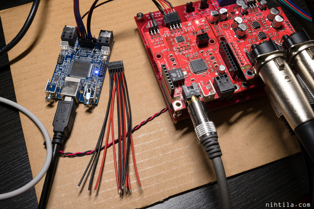
All I2S signals are connected on the pinheader and 5 V supply is taken from VD supply in Wee DAC.
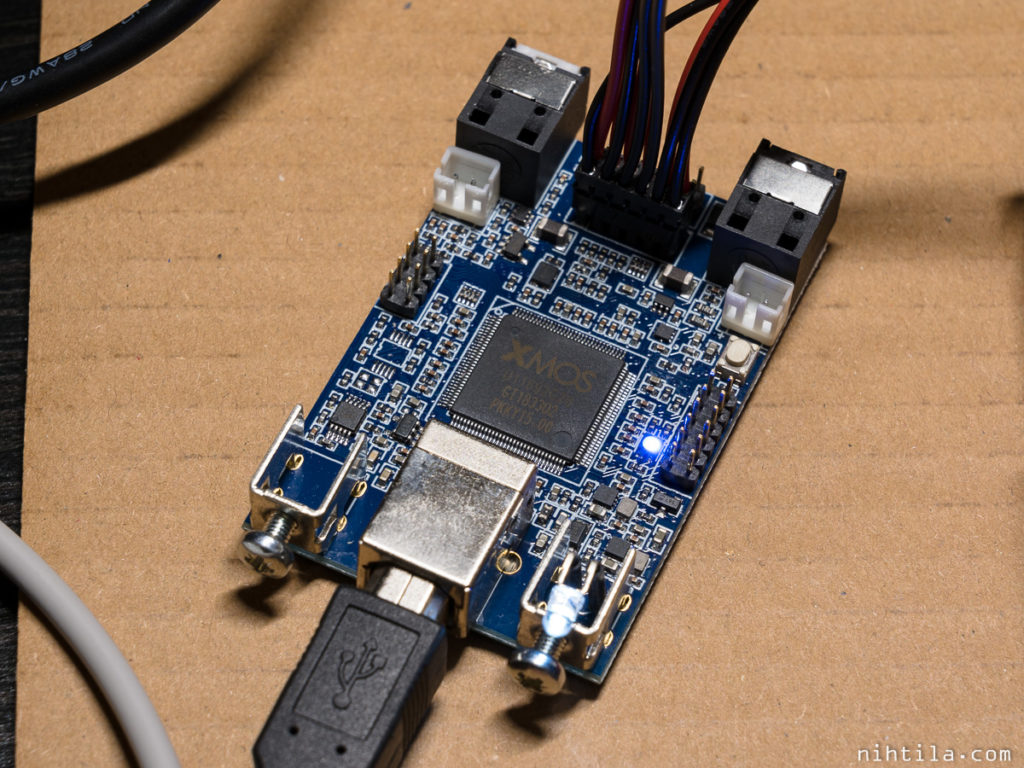
MCHStreamer
MCHStreamer configuration is done by uploading a correct firmware to support required formats. “AllRate” firmware is used here which supports 10 I2S channels in and out, and sample rate up to 384 kHz. None of the other formats are supported with this firmware, only I2S.
No configuration is needed on the board itself. I2S signals are available on small pinheader.
Measurements
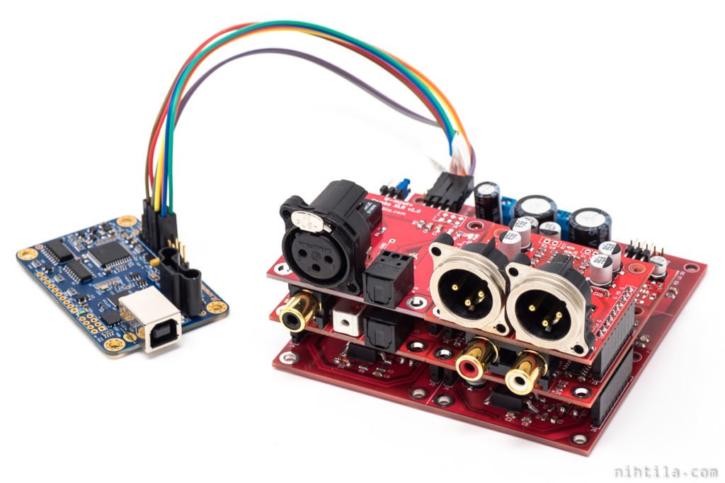
There is an awful lot of measurement that could be done due to extensive feature set and format support of both boards. However, as the purpose here is to find a mate for W-DAC, I have focused only on that. USB board is connected to I2S input of W-Input followed by W-DAC 4493. Thus, only PCM output from USB board has been measured here.
I have not run these tests at higher than 192 kHz sample rate for now, for two reasons. First, I don’t need higher sample rates at the moment. Second, APx software has a stupid restriction that although you can use higher sample rates with ASIO devices, you cannot run automated sequence with higher than 192 kHz sample rate. I have no idea why. So the standard set of tests I have cannot be run for higher sample rates. I can do manual tests and sweeps though.
Reference measurements – coaxial S/PDIF
Reference measurements were done using Coaxial S/PDIF input on W-Input, and 48 kHz sample rate. Single point THD+N and THD, Dynamic Range, and two FFTs have been taken as key specs here.
- THD+N, 997 Hz, -2 dBFS: -115 dB
- THD, 997 Hz, -2 dBFS: -121 dB
- Dynamic range: 120.6 dBA
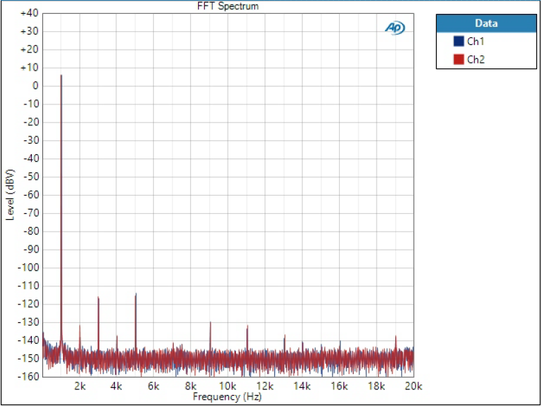
First FFT is 20 kHz bandwidth and 1 kHz 0 dBFS signal. This shows harmonics.
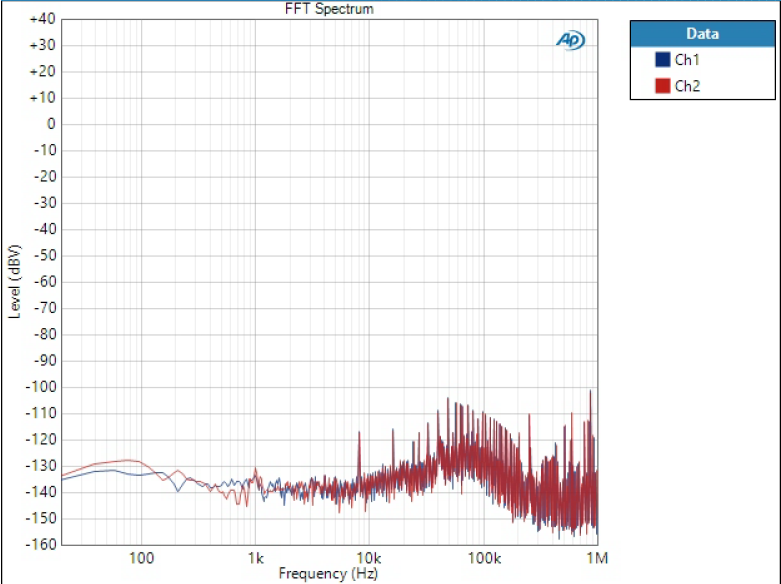
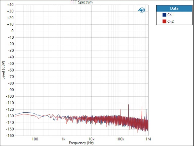
The other is 1 MHz bandwidth and no signal. This shows what happens in the noise floor over wider bandwidth. Those high frequency spikes are likely from the DAC itself but some also may be from outside world.

Next are the same measurements but using the USB to I2S board as input. I will start with I2SoverUSB as things were more straightforward with that.
I2SoverUSB results
- THD+N, 997 Hz, -2 dBFS: -115 dB
- THD, 997 Hz, -2 dBFS: -121 dB
- Dynamic range: 120.3 dBA
I took decimals in DR results as otherwise it would have rounded like there is 1 dB difference to reference, while in practice it is just 0.3 dB. Goes into measurement fluctuation.


1 kHz FFT is basically identical. There are slight changes in the 1 MHz noise floor. This one doesn’t have the spike at around 30 kHz. Not sure if that means anything.
Overall, no problems whatsover. Results are basically identical between S/PDIF and JLSounds board.
I also checked 44.1 kHz as it is different sample rate family. Gladly I can say those results are as great without any issues. Interestingly the 30 kHz tone was back, and along with similar tone at around 60 kHz. So that may be something that is fluctuating in there.
Likewise, results remain very similar and excellent at 192 kHz sample rate.
MCHStreamer results
I started with the same 48 kHz measurement as for I2SoverUSB.
- THD+N, 997 Hz, -2 dBFS: -113 dB
- THD, 997 Hz, -2 dBFS: -121 dB
- Dynamic range: 118.7 dBA
Ok, slightly lower results. Looking like noise is higher, deteriorating THD+N and DR.
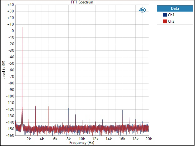
There are more tones in 1 kHz FFT although they are below dominant third and fifth harmonics.
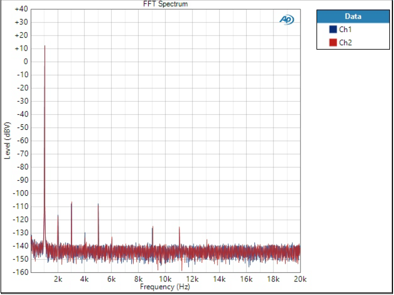
Ok, here things really start looking different. There is a lot of crap on high frequencies. Moreover, some tones are within audio band. In the above 1 kHz FFT it looks like those tones at 8 kHz, 16 kHz and so are there somehow because of the 1 kHz tone but in fact they are not. They are present even without signal. And those make RMS noise appear higher.
The big thing is that those tones are present there even when another input is selected in W-Input. It took me a while to realise that.
Anyway, it is clear that these are not problems in the signal itself but just the fact that this whole thing is connected to PC. At first I was thinking everything related to jitter due to lack of crystal oscillators but it seems this is all due to lack of galvanic isolation.
Furthermore, things get worse when sample rate gets higher. You can also see some sort of modulation sidetones in FFTs at times. Someone with more understanding could draw more conclusions from these. But for us next point is important.
I repeated the measurement keeping everything the same but using balanced output from W-Output XLR instead of single-ended RCA – and all that garbage is gone! Results look as follows; note 6 dB higher overall level.
- THD+N, 997 Hz, -2 dBFS: -115 dB
- THD, 997 Hz, -2 dBFS: -121 dB
- Dynamic range: 120.9 dBA
Some other tones visible in high end of 1M spectrum are also gone due to common mode rejection. As a tradeoff even harmonics are higher.
Anyway, regarding improvements over single-ended connection, the results remain identical with 192 kHz sample rate as well. So all that crap is really a result of some sort of crap on the ground which gets rejected with balanced connection.
Clock waveforms
Less important but I also had a quick look at the clocks with scope using my simple high-bandwidth DIY probes.
I2SoverUSB
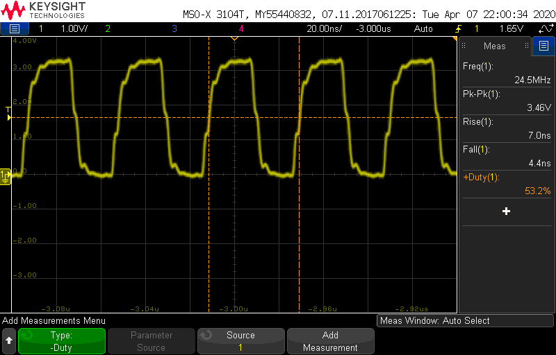
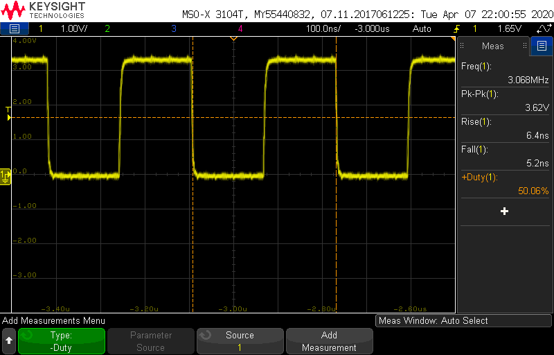
Clocks from the JLSounds board look good and clean. Here are three captures with 48 kHz sample rate, zoomed in.
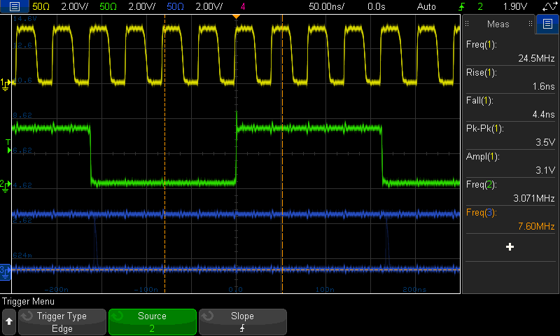
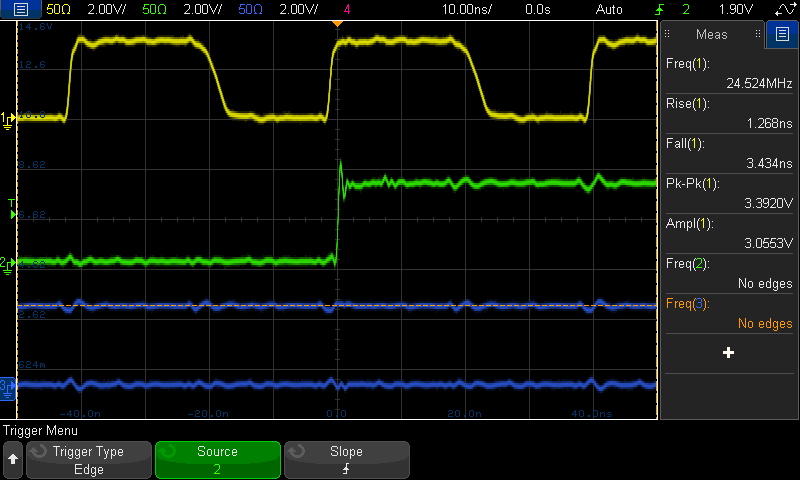
Falling edge of MCLK is quite a bit slower than rising edge.
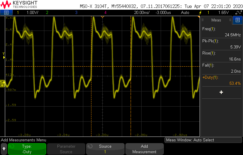
MCHStreamer
MCHStreamer has that ridiculous only one ground pin in the whole I2S pinheader, as opposed to I2SoverUSB doing it the right way having every second pin ground.
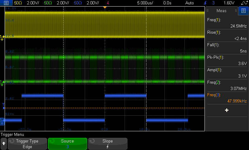
Therefore, clocks look uglier when coming in to W-Input:
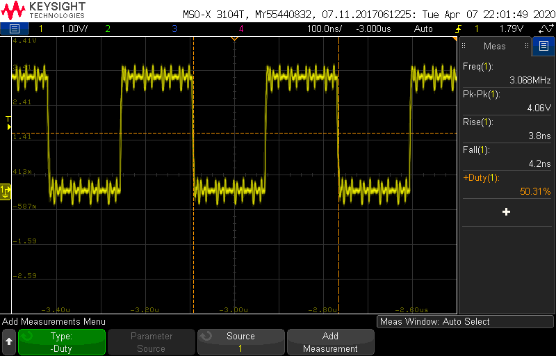
However, after I2S input switch (effectively a buffer) in W-Input the clocks look better. There are some steps visible in MCLK which I guess could potentially cause timing variations.
Note that none of these captures tell anything about clock jitter. Measuring jitter with oscilloscope would need a higher end scope.
Conclusions
Both of these USB boards can bring out the best W-DAC 4493 performance, not being the bottleneck in the system – and that is ultimately what you want. However, it is clear that lack of galvanic isolation in MCHStreamer may cause issues. In these tests all boards were just on my bench, wired to each other, without any enclosures or more thought given to grounding. I did try a combination of extra ground wires between Wee DAC, USB module, APx, and power supply, and in some cases I could see the in-band spurious components getting lower. So maybe with careful grounding and testing one can make these disappear. Or maybe they are not visible in all systems. But certainly a better bet is to choose a board that provides galvanic isolation. If galvanic isolation is not an option, balanced interconnection helps.
Another thing is the support for data formats and interfaces which is different between these two boards. Also, especially MCHStreamer can only support very limited combinations simultaneously so check the manual carefully before buying if you are after a certain combination of formats, interfaces, and sample rates.
Unfortunately only a very few USB boards can also record I2S, which is why I also have purchased MCHStreamer. The plan is to use it with ADC AK5572 in a recording application. I will carry out more tests later if these grounding issues are a real thing. If they are, I probably need to make a bidirectional isolator for MCHStreamer.
References and additional information
Version history
This page version history
- 11.4.2020 Initial version
3 comments
Thank you for this very useful and detailed report !
Regarding the JLsounds I2SoverUSB it’s not clear to me, which of the 2 MCLK outputs to use ?
I was a little confused about the manufacturers document (http://jlsounds.com/uploads/I2SoverUSB%20v.III.pdf)
because for the “AK4490 / Internal MCLK” he writes on Page 4:
“On MCLK_out_1 (H3.7) pin, one will have 22.5792MHz/24.576MHz MCLK. ”
but then on Page 9 I found for the “AK4490 / Internal MCLK” a table on how to
“Configuring MLCK_2 output” (headline above the table)
so I didn’t know if to use Pin H3.7 “MCLK_out_1” or Pin H3.5 “MCLK_out_2” for the correct masterclock for the W-DAC ?
which one is the right pin ?
Sorry missed this, haven’t got notification from all comments. It seems from the photo that I have used MCLK1.
Concerning the galvanic isolation I have question. Would it help to add a galvanic isolation adapter for the USB connection?
e.g. something like this
https://www.amazon.de/ICQUANZX-Isolator-Schutzisolation-ADUM4160-ADUM3160/dp/B07Z21RKMN/ref=sr_1_2?__mk_de_DE=%C3%85M%C3%85%C5%BD%C3%95%C3%91&dchild=1&keywords=galvanische+trennung+usb&qid=1611694209&sr=8-2
Comments are closed.