
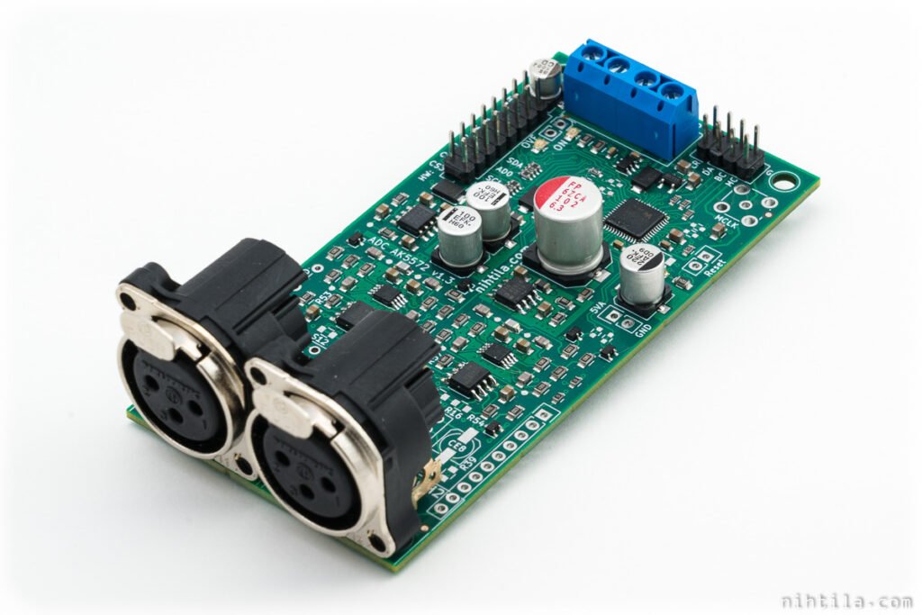
ADC AK5572 boards are available again, in slightly modified version 1.2. Despite a rather long list of changes there are no differences in performance and no major changes in functionality.
Note that there is also v1.3 now. It is the same as v1.2 except the PCB is green.
Changes are:
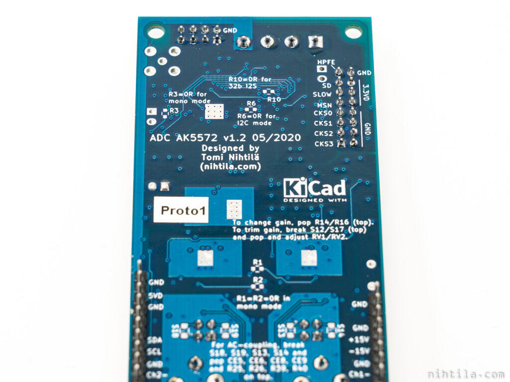
- XLR-connectors now fit completely on PCB
- Default maximum input signal is now 4 Vrms (instead of 3.6 Vrms) to align with other boards
- 4 Vrms possible in single-ended signal as well; in v1.1 input protection clipping prevented this
- No reset button, just header
- Screw terminal for supplies
- Changes in default component population and settings
- Input AC-coupling is now optional and uses bipolar electrolytics
- Jumper header is unpopulated by default
- ADC is I2S Slave without any jumper (opposite in v1.1)
- Digital high-pass filter is enabled without any jumper (opposite in v1.1)
- 32-bit I2S option removed from header and now set by 0R resistor
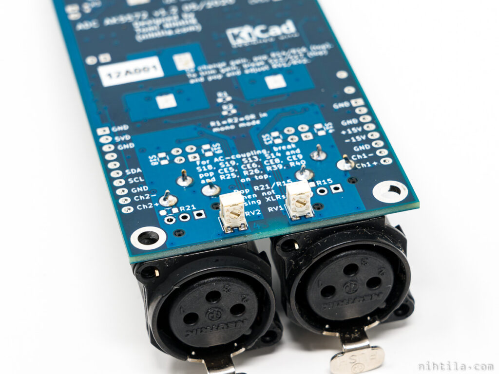
- Possibility to configure input buffers as instrumentation amplifier and use bottom side trimmer to adjust gain
- Wee DAC headers added at edges so that Wee DAC power supply board can be used
- Changes in input protection
Despite this list, for majority of users using the board remains exactly the same. Old feature list from v1.1 still holds:
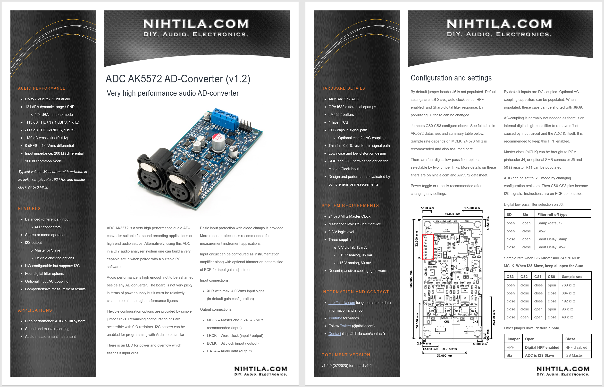
- Up to 768 kHz / 32-bit audio
- Very high (measured) performance, typically:
- 121 dBA dynamic range / SNR (124 dBA in mono mode)
- -113 dB THD+N (-1 dBFS, 1 kHz)
- -117 dB THD (-8 dBFS, 1 kHz)
- -130 dB crosstalk (10 kHz)
- Balanced differential input
- Stereo or mono operation
- I2S output; Master or Slave
- HW configurable (supports I2C as well)
This post focuses on differences between v1.2 and v1.1. For basic information refer to the original ADC AK5572 v1.1 post.
Design
Here are some of the changes explained in more detail and what it means.
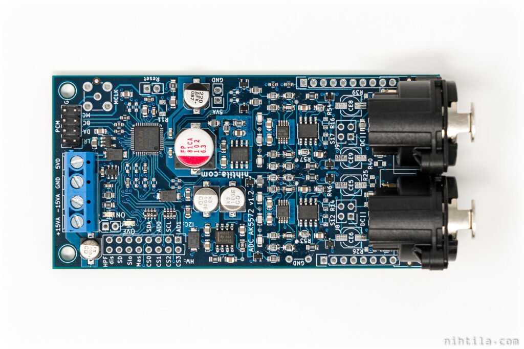
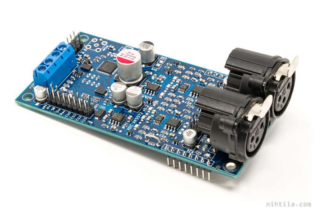
PCB
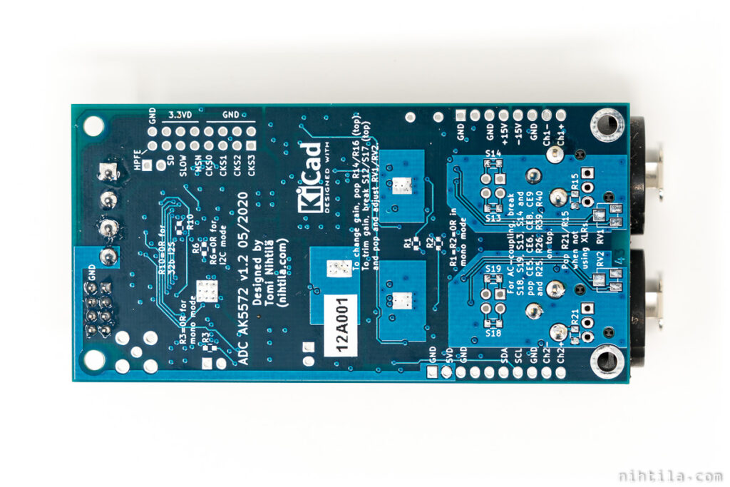
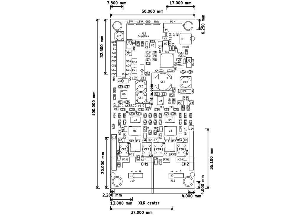
Board dimensions are the same (5x10cm, 4 layers) and major blocks are almost unchanged. Main difference is that now XLR connectors fit completely onboard and are populated by default.
Edit 02/02/2021. There is also a version 1.3 which is the same as v1.2 except the PCB is green and there are some minor changes in manufacturing the board. Everything here holds also for the v1.3.
Input circuit
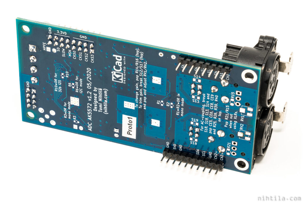
AC-coupling capacitors are not populated by default but shorted with shorting links on bottom side. If capacitors are soldered, these links must be cut with a knife. When capacitors are in place, they can be shorted with jumper links on 2×2 header. Capacitors are now 10u bipolar electrolytics as opposed to 1u plastic caps in v1.1. Lower 1u capacitor caused odd low frequency noise behaviour on some boards. If you’ve got your v1.1 ADC with 1u cap don’t worry, then I didn’t see any issues with your board. As a workaround some boards were shipped with 33u through-hole bipolar electrolytic. In most cases AC-coupling caps are not needed (hence not populated by default) as digital high-pass filter takes care of small DC.
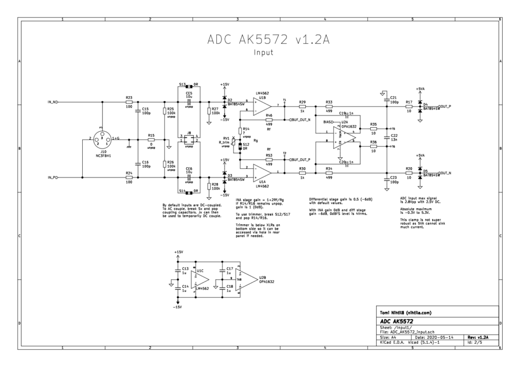
Input buffers are still the same by default. However, now there is a possibility to use them in instrumentation amplifier configuration. Furthermore, bottom side trimmer potentiometer can be used to adjust gain. This is all really for people who need this customisation, normally it is not used or needed. They are mostly for professional/studio use where gains may need to be trimmed. There is still a limitation that this gain control mostly allows increasing gain and supporting very high signal level (where attenuation is needed) with adjustable gain may not be suitable. This was more of a proof of concept to see if such trimmer configuration impacts audio performance – luckily not.
Differential amplifier stage is the same but gain is now 0.5. As ADC input range is 2 Vrms (1 Vrms per input), this gives 4 Vrms input range to this whole circuit.
There are changes in input protection. Major outcome of this is that 4 Vrms single-ended signal can now be used for maximum ADC input. In v1.1 max 2 Vrms single-ended signal was usable. Input protection is still not as robust as I want so there will still be some changes in future revisions. It doesn’t matter in normal audio use but I’d like the input to withstand almost whatever is thrown at it.
This is an evolving design and gain trimming and input protection will likely see more changes in the future.
Configuration pinheader
Large pinheader with jumper links to change settings is not populated by default now. This along with some other changes (especially use of Shorts instead of 0R resistors) saves time in assembly. To offer better default settings without the header, HPF and Master/Slave settings were inverted. The same settings are still available when the header is soldered and jumper links used. Except 32-bit I2S setting that was removed due to space constraints, and moved to be a resistor setting. After all, it doesn’t matter if I2S is 24-bit or 32-bit; there is no more information.
Settings are now as follows.
Clock configuration
| CS3 | CS2 | CS1 | CS0 | Sample rate |
| open | close | close | open | 768 kHz |
| open | close | close | close | 384 kHz |
| close | close | close | close | 192 kHz |
| close | close | open | open | 96 kHz |
| close | open | open | close | 48 kHz |
When in I2S Slave mode (default), it is recommended to keep all CSx links open for automatic clock setting.
Digital filter
| SD | Slo | Filter roll-off type |
| open | open | Sharp (default) |
| open | close | Slow |
| close | open | Short Delay Sharp |
| close | close | Short Delay Slow |
Other settings
| Jumper | Open | Close |
| HPF | Digital HPF enabled (default) | HPF disabled |
| Sla | I2S Slave (default) | ADC is I2S Master |
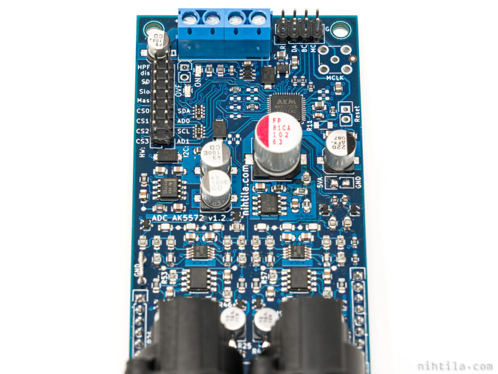
In addition, support for Wee DAC edge headers was added. There is not really an application for that yet except that the PSU baseboard could be used as a power supply for the ADC.
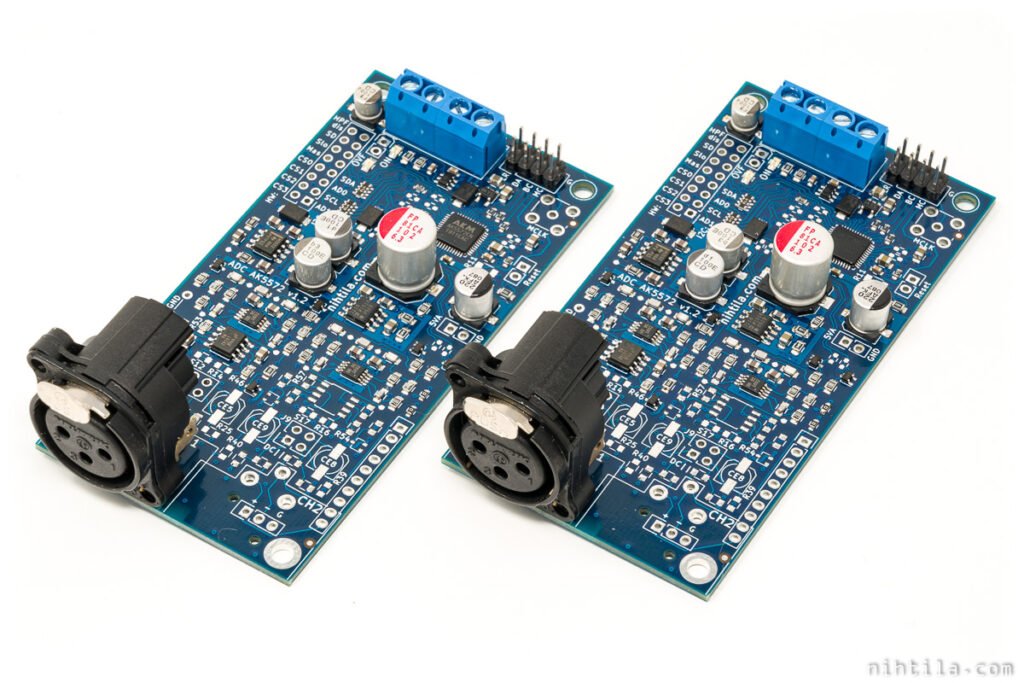
Dual mono operation
Mono operation is still available for creating a dual mono ADC. It improves SNR and DR by 3 dB but comes at a cost as mono board costs almost the same as a stereo board. There is not really improvement in crosstalk as it’s already almost unmeasurable in stereo board due to completely separate circuits for channel 1 and 2. However, dual mono always remains as an interesting design philosophy in my opinion.
Measurements
Audio performance is on par with version 1.1. Based on a test batch of 7 boards there are no statistically significant differences.
Input level
By default the maximum input level that gives 0 dBFS digital signal is 4.0 Vrms. This aligns with other nihtila.com boards that use 4 Vrms level in balanced connections. In v1.1 maximum input level was 3.6 Vrms.
Another difference is that now input works as “true differential” in a way that one can get the maximum level with single-ended signal as well. So the ADC happily takes in 4 Vrms single-ended input signal. In v1.1 this was limited to 2 Vrms due to input protection clamps.
Power consumption
Power consumption figures are slightly changed, typical figures for stereo board being:
- 5VD: 12mA
- 15VA: 95mA
- -15VA: 57mA
This means that the board does get significantly warm.
Files
References and additional information
- ADC AK5572 v1.1 page with more product info and also video
- 2-page factsheet
Version history
Schematics / PCB version history and known errors and bugs
- v1.1A Initial version
- v1.2A is what this post discuss about and lists changes
- v1.3 Electrically the same as v1.2 but manufactured slightly differently and the PCB is green.
This page version history
- 5 July 2020 Initial version
- 2 February 2021 Added comments regarding v1.3.
See shop page for purchasing instructions.
24 comments
The amount of skill, work, time and passion that you give to your products is outstanding!
I’m very impressed!
I received a board from Tomi. Incredible piece of work.
Still waiting an I2S receiver in order to test it. Can’t wait.
Is it possible to select 44k 24 bit as most recording engineers run in this format.
This was replied to email a while ago but just for records to mention here, yes 44k is possible. It just means Master Clock to the ADC must be an integer multiple of 44.1k, for example 22.5792MHz, as opposed to 24.576MHz for 48k family of sample rates.
I received my AK5572 v1.2 (bought on Tindie),
and i have to say that it is of exceptional quality.
Not only the circuit board, hardware etc .. but also the sound quality is outstanding. It doesn’t have to hide behind other “high end” ADCs in any way, the opposite is the case
One or the other will be interested to know that Lyuben from jlsounds.com is planning to release an I2S to USB converter.
(in the same high-quality design and quality as his well-known “I2SoverUSB v.III” converter)
That would be the ideal complement for this ADC,
since the “miniDSP MCHStreamer” doesn’t convince me in terms of quality –> http://nihtila.com/2020/04/11/jlsounds-i2soverusb-and-minidsp-mchstreamer-usb-to-i2s-boards-with-w-dac/
Thank you for your comments Dirk.
And that is very interesting news regarding JLSounds! I get lots of questions how to connect this ADC to PC, and I’d love to see a good solution by JLSounds to recommend. Do you know if there is more information somewhere? Maybe I could try to contact him directly as well.
there’s nothing ob his homepage or elsewhere in the web,
but month ago (in May 2020) I asked him directly via email if there is (or will be) an I2S->USB solution from him as well.
He answered that he has in fact plans for “I2S input to PC”, and that this might eventually be ready “after summer holidays” … 😉
Just bought the V1.2 of the AK5572 ADC.
It’s a great product. I am using it with DIYINHK XMOS USB TO/FROM I2S to capture analog signals. The FFT shows the board reach the published specs by Tomi.
I can say with really high confidence, you can not buy anything better in term of THD and THD+N in the market, in this bandwidth, no matter how much you will pay unless you buy an Audio Precision or some special Agilent/Kesight hardware.
For Tomi, what I can say, you probably know he is extremely kind and reachable and helpful.
I am strongly recommend his ADC board.
If you know how to manage you can make this board a really good DAQ
Best,
Guy Cohen
Thanks a lot Guy!
@Guy:
do you use this one ?
https://www.diyinhk.com/shop/audio-kits/170-xmos-32bit-384khz-dxd-dsd256-usb-tofrom-i2sdsdreclock-spdif-pcb.html
did you manage to get I2S input 384kHz via USB to the PC ?
which driver did you use ?
Yes Dirk, that what I am using.
Actually I do not use a driver as I am working with Mac Os. Clearly, in DIYINHK website you can download a suitable driver for Windows.
Note that the card from DIYINHK is only in master mode. I used the AK5572 in slave mode and capture the signal via USB by Audacity.
Then checked the FFT by Audacity or by Matlab.
It is working great.
Best,
Guy
[…] I contacted him and bought some of his pre-tested boards for handling the analog stuff. I got two ADC AK5572 to be able to support four input mono channels and three W-DAC S 4493 to support three stereo […]
@nihtila
Great work!
Does the input sensitivity allow to directly connect a MM or MC phono-cartridge and use digital gain with full dynamic range of vinyl?
Will there be a version with 48V phantom power for microphones?
Input sensitivity is 4Vrms by default but could be lowered a little – although likely losing a little bit of dynamic range. I’m not a phono user myself so not sure what sort of signal level you expect to get from those cartridges and what is the dynamic range. But if you know, you could roughly calculate it knowing the DR of the ADC is around 120dB. If you need 40dB gain, is that enough headroom for vinyl? It is an interesting idea though.
I’m not planning to add phantom power.
Vinyl recordings have a maximum dynamic of 50 to 60 dB.
The AT3600 is the most common cheap MM-cartridge.
Audio Technica AT3600L Phono Cartridge Specifications:
– Output voltage: 4.2 mV
– Frequency response: 20Hz-20kHz
– Channel balance: 1.5dB
– Channel separation @ 1kHz/10kHz: 24/15dB
– Tracking force: 2.5 – 3.5 g
– Stylus type: Highly polished and shaped .0006 inch conical diamond
– Stylus construction: Bonded round shank
Datasheets of Ortofon MC-cartridges:
https://www.ortofon.com/mc-series-p-704
Is it possible to adjust input buffer impedance and capacity of the ADC AK5572 Board?
I cannot say about the microphone but I guess you could calculate an estimation. Preamp would likely be a good idea anyway.
Input impedance is basically determined by input resistor so it can be adjusted by changing these resistors. What do you mean by capacity? If capacitance, there are some capacitors at the input, seen in schematics.
Hi Renne,
to use any ADC or amplifier with phono you need preamplifier with RIAA correction.
The best and chip one is developed by Nick Suhov last year.
Best regards.
Does a microphone with -37mV/Pa achieve a dynamic range of 106 dB with the ADC AK5572 or is a microphone preamp necessary?
Hi,
Do you plan to produce more ADC v1.3 boards in near future?
I replied to you, must have gone to spam :/ Not sure why some of my emails are marked untrusted, even tried to sort that with my hosting. Need to contact them again. Anyway, there will be more ADC boards (and other boards) but that is likely in the beginning of 2023 or so.
looks like it didn’t reach my email 🙁 checked spam, but no message. but it’s wider problem, and don’t know what causing it.
either way – good to know. 2023 is not that far away 🙂
Hi Tomi,
very nice work! I’m very impressed by your projects (ADC and DAC as well). I plan to buy a set of both for some measurement equipment. But I’m a bit confused how you connected they both to the PC to make measurements.
Can you please reference which devices you’ve used for this nice ADC board and for your W-DAC v2?
Best regards,
Dimitrij
Hi Dimitrij
This is a bit of a gap as I don’t have my own USB-module, and there are not many supporting recording in general. MiniDSP MCHStreamer is a rare unit that supports both.
Comments are closed.