
PCM I2S to S/PDIF digital audio converter to convert I2S serial audio data to S/PDIF with coaxial, Toslink, or AES/EBU connection.
- Sample rate 48 kHz, 96 kHz, or 192 kHz
- I2S input
- SPDIX TX is always I2S Master
- Supports ‘Dual Mono’ mode with 2x ADC AK5772 in Mono mode
- Two S/PDIF output connector options; all are galvanically isolated
- Coaxial RCA and optical Toslink
- Balanced XLR AES/EBU
- Assembled boards available
Introduction
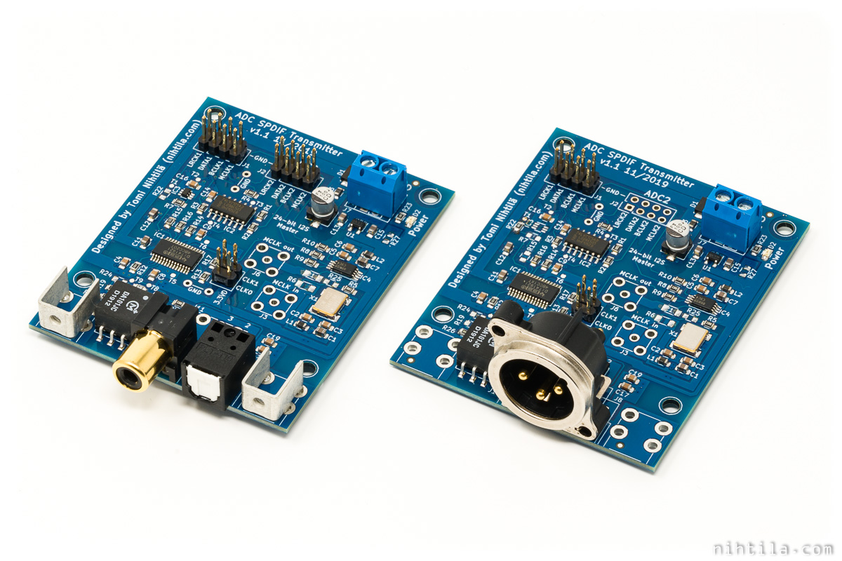
SPDIF TX is an I2S to S/PDIF digital audio converter. It takes in I2S serial audio data in either conventional stereo format or specific dual mono format used in ADC AK5572 AD-converter. In dual mono mode SPDIX TX takes in two stereo (in ADC AK5572 dual mono mode both channels have identical data) streams and picks one channel from stream 1 and the other channel from stream 2.
The board supports common audio sample rates of 48 kHz, 96 kHz, and 192 kHz. That is the only onboard setting available to the user, everything else is handled automatically by the circuit.
Due to ADC AK5572 support, the board is limited to I2S Master operation only.
Design
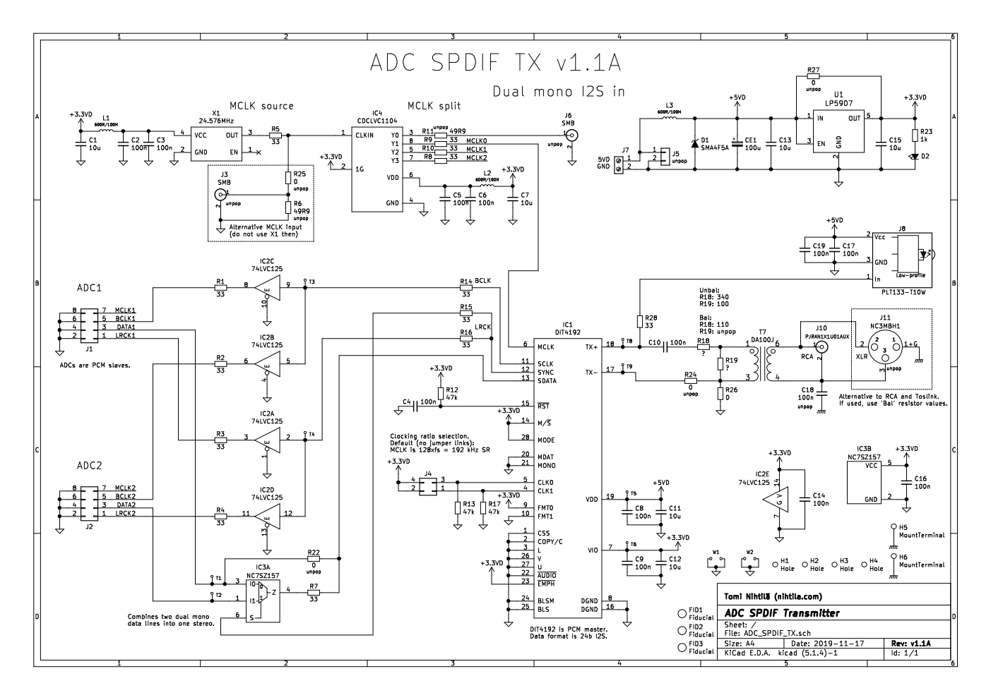
See schematics below or schematics walkthrough in the video above.
I2S input can be a single header for stereo use or dual header for mono use. In both cases all clocks are coming from the board and buffered. Only Data direction is from source to SPDIF TX. In stereo mode Data goes directly to DIT4192 digital audio transmitter. In mono mode MUX clocked by word clock picks first channel from ADC1 connector and second channel from ADC2 connector. This is the support for 2x ADC AK5572 in mono mode.
There is an onboard 24.576 MHz oscillator. Optionally, external master clock can be used. Clock is split by a dedicated high quality clock splitter to one or two sources and DIT4192. There is one extra clock output to use elsewhere in the system.
S/PDIF output is split into Toslink transmitter and transformer isolated electrical output which can be unbalanced RCA or balanced XLR. Different resistor values are used for each to match different impedance and output level requirements.
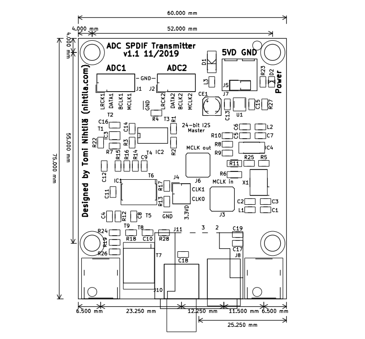
PCB
PCB is squeezed into 2-layer 60 mm x 75 mm design.
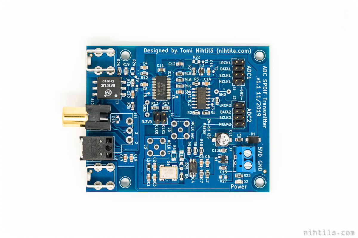
As usually, schematics and layout have been done with KiCad and PCBs ordered from Elecrow. Components are sourced from Mouser and Digikey. Boards have been assembled using my DIY reflow oven.
Configurations and settings
Inputs will be configured for stereo or dual mono use when assembling the board. Similarly, output will be configured for RCA or XLR in assembly.
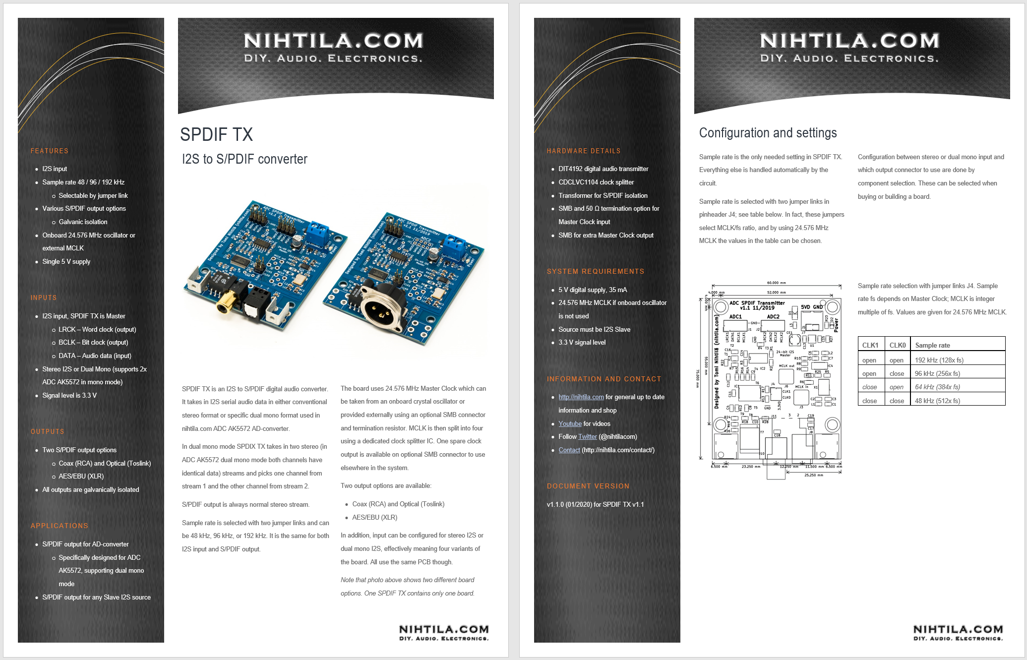
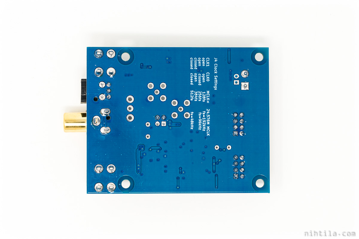
The only setting for user is the sample rate, provided with two jumper links on J4:
| CLK1 | CLK0 | Sample rate |
| open | open | 192 kHz (128x fs) |
| open | close | 96 kHz (256x fs) |
| close | open | 64 kHz (384x fs) |
| close | close | 48 kHz (512x fs) |
Sample rate is tied to Master Clock and the values given are with 24.576 MHz clock. For other clocks, use the multiplier given.
System requirements
Input I2S device(s) must be Slave and logic level 3.3 V.
A word of caution that the clock buffers used are quite fast and can cause ringing and signal integrity issues with bad connections. As always with I2S, cables should be kept as short as possible. It is only meant for going from a board to another next to it.
The board requires only single 5 V supply with maximum current draw of 35 mA.
Measurements
Measurements have been done when making sure the board works as expected but there is not much to show here. After all, it is a digital board.
Something to mention are S/PDIF output levels in electrical outputs:
- Unbalanced RCA: 0.5 Vpp into 75 ohms
- Balanced XLR: 2.5 Vpp into 110 ohms
References and additional information
- 2-page factsheet
- Product video
- ADC AK5572 AD-converter this board was designed for
Version history
Schematics / PCB version history and known errors and bugs
- v1.1A First released version
This page version history
- 3.2.2020 Initial version
1 comment
Hello,
I’m sketching an idea to hack the Ikea Sonos Speakers a little bit more. Someone already used the analoge output ot the Internal DAC (PCM5101A) to feed it in an Extertal amplifire. (see the link)
https://www.instructables.com/Cheaper-Sonos-Architectural-With-IKEA/
I do have some big aktive Speakers which have an Digital input (Spdif and optical) so my idea is to connect your Board to the Internal I2S bus of the Ikea smart Speakers. (and mybe de-solder the Internal PCM5101A).
Do you see any Chance that this could work?
Best Regards
Oliver
Comments are closed.