
- 6-channel analog output module for Roland MV-8000/8800; mimics analog part of Roland MV8-OP1 module
- Digital signal and supply connector with identical pinout to the original
- Same output level as the original
- High performance
- SNR: 118 dB (A-weighted)
- THD+N ratio: -103 dB min, -93 dB max
- Crosstalk: -112 dB max
First I must say I have never even seen Roland MV-8000/8800, this is a bespoke project based on given interface and manufacturer service manual. I have developed, tested, and measured it in isolation but have been reported it does work on Roland MV-8000. However, I have not been able to compare performance measurements to the original one.
If you are interested in getting one, scroll to the end of the post.
Design
Original MV8-OP1 is a relatively straightforward design with following parts:
- 34-pin ribbon cable connector to the main unit, this contains all supplies, digital audio signals, and control signals
- Three stereo DAC circuits with analog output stages
- Mute circuit to soft-mute DACs and hard-mute outputs
- There is also digital part which is not included in this clone
MV8-OP1 uses AK4393 DACs followed by OP275 opamp stages. One opamp is used as differential amplifier, another one to invert the cold lead signal. There is no fancy filter structure included, just simple low-pass around opamps.
As this is a bespoke design, unfortunately I cannot publish full schematics. However, it is mostly a copy of the original with some slight changes. Below are schematics of one output pair and some background explanation of the chosen solution.
DAC circuits
Original MV8-OP1 uses discontinued AK4393 DACs. This is a very high-performance, 120 dB max SNR and -100 dB THD+N IC. However, I am not sure MV8-OP1 unit achieves these numbers due to large resistors in the output stage. It also seems a bit odd that output specifications of the main unit MV-8000 are a lot weaker than MV8-OP1 due to lower quality codecs.
Here AK4393-compatible AK4396 is chosen. It has similar specs and is also discontinued but vendors still have stock left. It has some extra features such as I2C compared to AK4393 but is fully compatible in parallel (hardware) mode. External components are pretty much from the original design and datasheet except the analog stage.

DAC circuit and analog stage
Output stage
Output stage goals were following:
- 5 Vrms (!) output level as in the original MV8-OP1
- Not much worse than 100 dBV (10 μV) noise floor, giving SNR in the order of 110…115 dB
- Second order filter
- No electrolytics in signal path (although original design has) – I just think they don’t belong there although by choosing very large value it should have no impact
- Differential amplifier to get rid of common-mode DC
- Differential DC from DAC is small enough
- AC load should not be under 1 kΩ (according to DAC specs)
- Relatively simple to keep cost and PCB space under control
- Mute transistor circuit copied from original design
AK4396 has two 2.8 Vpp differential voltage outputs centered at 2.5 V DC level. This gives total voltage swing of 5.6 Vpp = 1.98 Vrms. Therefore, required gain is 2.5.
I wanted to make a second order Butterworth filter in the analog stage. This could be done with Sallen-Key or Multiple Feedback (MFB) filter topologies. I am not a filter expert but Sallen-Key has some advantages such as equal component values in some filter components, easily changeable gain, and lower noise gain. MFB may have better distortion charasteristics in low-pass filters (less capacitor distortion), and it is easily implementable using fully differential opamp.
Why fully differential opamp? I just think it fits well in this design, considering the filter. The best choice would probably be to use single-ended Sallen-Key filters on positive and negative output. Then we could use two more amps or fully differential amp to remove DC and create hot and cold outputs. Therefore, it would need one more opamp per output than the chosen solution. Noise could be a bit lower although 1 kΩ load limit for DAC still restricts resistor values – in order to get really noise, resistor values must be in hundreds of ohms instead of thousands. However, extraordinary high output level means there is higher gain anyway.
I believe chosen fully differential MFB filter offers good compromise here. With one single amp per output we get rid of DC, get second order filter, and fully differential output with hot and cold actively driven. The compromise is that with the required gain and 1 kΩ limit we cannot use very low resistor values which would have positive impact on noise. For example, R15/R16 is the dominant resistor so 1k is not too bad. We would want to make R10/R11 large and R15/R16 small but this is just not possible.
I have included placeholders for 100 uF electrolytics just in case but they are not needed. Original MV8-OP1 has these so it made me a bit suspicious are they needed for some reason. For example, is it possible to (accidentally) create DC-signal with the synthesiser?
2SC4213A transistors at output are part of the mute circuit also found in the original MV8-OP1.
Layout
Board size is 130 mm x 110 mm and schematics and layout have been done with KiCad and PCBs ordered from Elecrow. Components are sourced from Mouser and Digikey as Mouser does not source AKM chips.
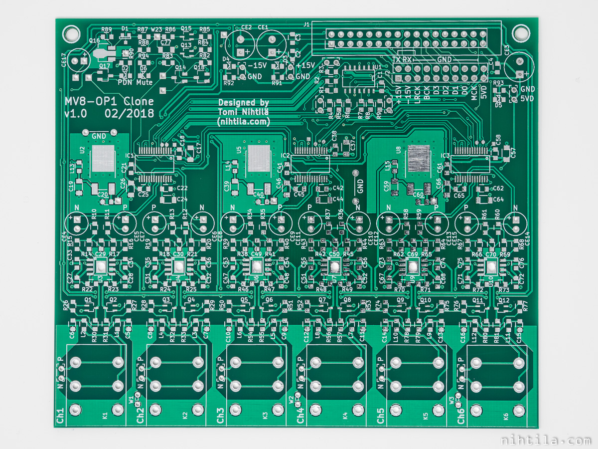
PCB top
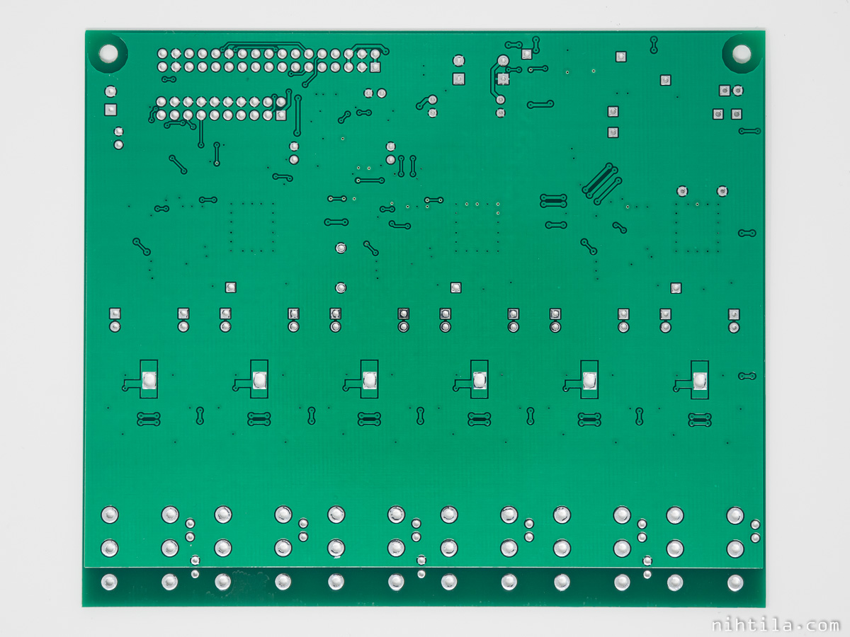
PCB bottom
There are some not-so elegant DIY tricks on the layout. LME49724s have thermal pads which have been soldered using holes. This is a way to make it easy to solder thermal pads under IC with soldering iron instead of hot air. However, this cannot be used when boards are populated in factory.
LME49724 thermal planes are tiny but enough, I have used these opamps also without thermal pad connection. Overall, due to thermal connections the whole board gets slightly warm.
Measurements
I have measured the board at work using Audio Precision APx555 audio analyser. Unless otherwise mentioned, measurement bandwidth is 20 kHz and frequency in single-tone measurements is 1 kHz.
As I do not have Roland MV-8000/8800 synthesiser, all tests are performed in isolation where this board is powered by bench PSU and signal source is APx. While measurements in the end application have not been possible, I have got the confirmation that the board is functional. Therefore, it can be assumed the performance is very similar if not identical.
APx signal format in measurements is MSB-justified, 24-bit, 44.1 kHz, and MCLK = 384 x Fs = 16.9344 MHz; as far as I know this is the format MV-8000 uses.
Measurements have been run in channel pairs 1&2, 3&4, and 5&6. Therefore, for example crosstalk is just between those two channels and not across all channel combinations. No major differences between channel pairs was seen.
One more thing to note is the extraordinary high maximum output level Roland uses – full-scale level is 5 Vrms. Therefore, some tests have been ran with 0 dBFS but also with -14 dBFS which corresponds 1 Vrms. In many cases user probably has some attenuation set in the synthesiser anyway.
Key figures
Only one figure per parameter is given here. Differences between channels are insignificant.
- Gain: 4.9 Vrms/FS
- DC-level: max 3 mV
- THD+N ratio
- 0 dBFS: -93 dB
- -14 dBFS: -101 dB
- Noise level: -102 dBV
- SNR:
- 116 dB non-weighted
- 118 dB A-weighted
- Crosstalk at 10 kHz: -112 dB (the worst channel, most channels around -115 dB)
THD+N in detail
Below are THD+N graphs and although results are good, it is notable that THD+N starts rising relatively early, already around -15 dBFS.
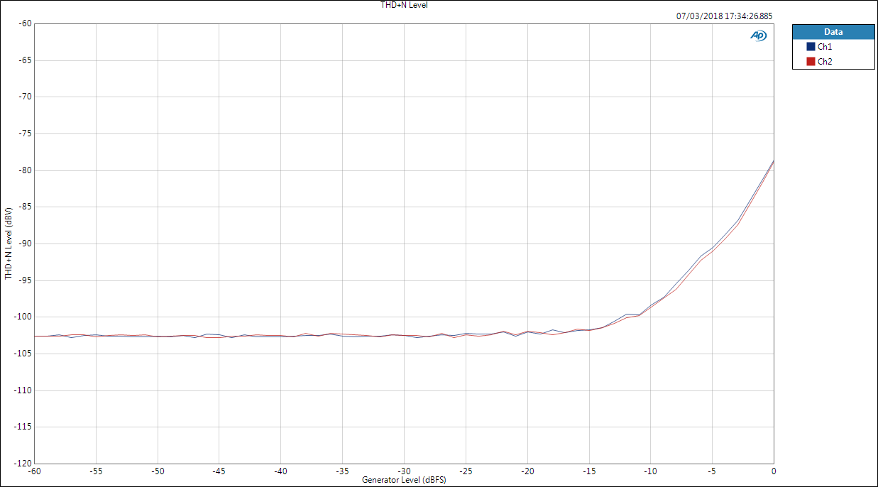
THD+N level vs. input level
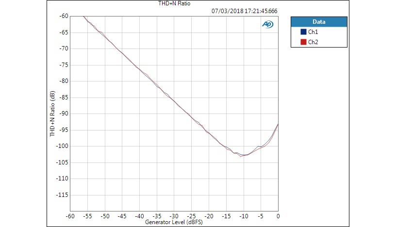
THD+N ratio vs. input level
I had extra measurements in my script separating THD+N and THD, where latter only includes harmonic components without noise. The results are following:
- 0 dBFS level:
- THD+N ratio: -93 dB
- THD ratio: -93 dB
- -14 dBFS level:
- THD+N ratio: -101 dB
- THD ratio: -110 dB
This tells that at 0 dBFS, distortion is the dominant factor – distortion increases, not noise. At -14 dBFS noise is the dominant factor which is usually the case at lower signal levels. AKM does not have graphs in their AK4396 datasheet, only single figures, but they do have them in the evaluation board manual – and this graph shape is indeed a feature of the DAC. Shown graphs have similar shape. I do have to admit the peak value at 0 dBFS on their measurements is few dB better than mine so it is possible other circuit components are adding some distortion as well, considering signal level is very high at 0 dBFS.
After all, despite Roland using this extraordinary high signal level for some reason, there is actually some attenuation in place in normal use. Therefore, signal level is usually lower than 0 dBFS.
Conclusion
Unfortunately I do not have the original MV8-OP1 so I cannot compare the results. However, measurements are very good, especially if using signal level slightly lower than full-scale – which I believe is always going to be the case.
Buying boards
If you are interested in getting one of these boards, contact Max Staack (maxmatteostaack (a) gmail.com).
References and additional information
- Roland MV8-OP1 product page
- Roland MV-8000 product page
- AK4396 datasheet
- AK4396 evaluation board manual
Version history
Schematics / PCB version history and known errors and bugs
- v1.0A Initial version
This page version history
- 9.4.2018 Initial version published
6 comments
Is the op1 clone available to buy ? Can’t find a roland op1 nowhere at all for my mv8800 , if so how much?
Hi Cliff
I do not have any boards myself as this was a project to someone else. There is a contact info at the end of the post, you can ask him for boards and how much they are.
where can i buy
where can i buy
Hallo,
Kan ik hier zo’n MV8-OP1 KLOON kopen voor de MV8800?
dc offset when looping. when making loops you can get clicks so perhaps they added capacitors to tame/attentuate that behaviour because the clicks on looping, with the MV, are suppressed.
Comments are closed.