This is an updated version of my old miniD preamp from 2014 combining miniDSP and 4-channel DAC-preamplifier
- Small 4-channel preamplifier with digital signal processor and digital-to-analog converter
- DSP can be used for crossover for 2-way speaker or between speaker and subwoofer, and/or digital room correction
- 4 digital SPDIF stereo inputs and one analog input
- 4-channel unbalanced analog output
- DSP-solution consists of ADAU1701-based miniDSP-board and applicable software
- Atmel AVR-based firmware with extensive features such as IR-remote, balance, offset for inputs and outputs, DSP bypass, selection between analog or digital volume control, etc.
- Main components: SRC4392 SPDIF-receiver and sample rate converter, miniDSP-board, PCM4104 DAC, OPA1662 op-amps and PGA4311 volume control
The concept here was to design a motherboard for a DSP board, similar way as in SharcDSP but this is a complete 3-in-1 device containing DSP, DAC, and preamplifier – all that is needed for active speakers. The board was designed in 2014 and is a bit “older” design in a way that these days I do things slightly differently. However, it is fully working and also measures reasonably well. I have now written completely new firmware for it and everything works fine.
This is not really a project someone can easily follow and build but more for reference what can be done with miniDSP. I do have spare PCBs if you want to accept the challenge!

Connectors, some are in my board and some in miniDSP
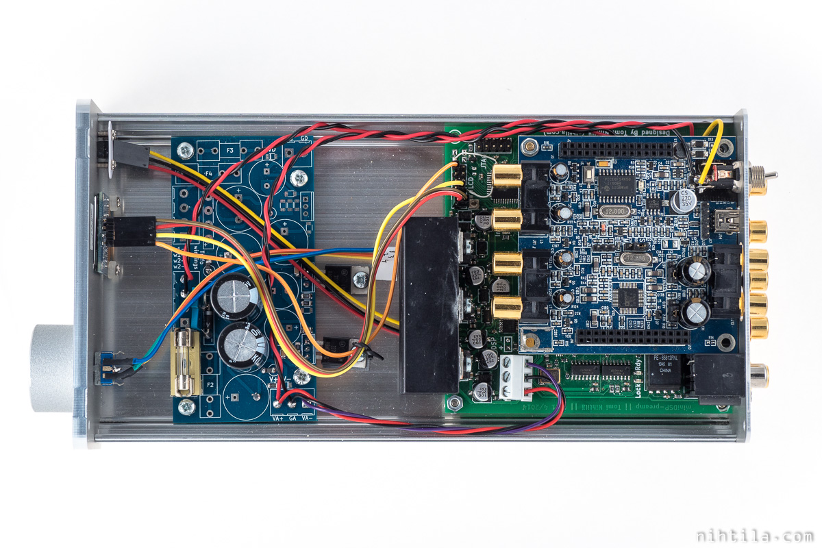
Blue miniDSP board sits on my green preamp-board
My miniDSP-preamp board
Before going to my design, let’s introduce miniDSP. If you know what it is, you can skip this.
What is miniDSP?
The name miniDSP refers to a company in Hong Kong who are developing and manufacturing audio DSP-solutions for hobbyists and OEM-manufacturers, but it is also a name of their famous inexpensive DSP product based on Analog Devices ADAU1701. The board can be obtained encased or as a bare board. MiniDSP is a simple 2-input/4-output board with on-chip AD- and DA-converters, thus offering analog RCA connectors.
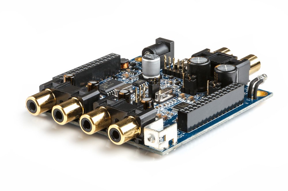
miniDSP 2×4 Kit, https://www.minidsp.com/products/minidspkits/2-x-in-4-x-out
User manuals and datasheets with connector pinouts are provided but schematics are not. Some boards are a lot more complicated and aimed at OEM customers, also requiring a lot more extensive electronics knowledge. However, miniDSP encased is a complete product and using it is relatively simple. Obviously some audio engineering understanding is required to manually tweak the filters as this is not a push-the-button solution.
The functionality and ease of use is actually provided by the PC software they call plug-ins. These are sold separately from the hardware and the plug-in defines what you can do with the board. I do assume they are all similar though.
So what can you do with it?
Plug-in main screen below gives a good overview block diagram of the device. You have two channels in, parametric EQ for each of them, then crossover filters to divide each channel into two, and again parametric EQ for each channel, and delay/gain stage at the end. Therefore, you can do crossover filtering and parametric filtering using biquads. This can be for example digital room correction I am interested in.
The second channel pair can also be used as a mono for 2.1 operation.
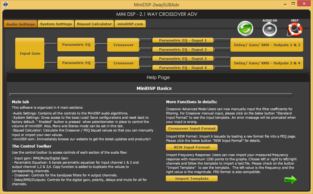
miniDSP 2.1 way crossover advanced plugin
Digital room correction
While some use miniDSP for their 2-way DIY speakers to perform crossover filtering, I have been using it for subwoofer filtering and acoustic room correction. Internally miniDSP has programmable digital biquad filters. These 2nd order recursive filters can be cascaded, thus offering possibilities for very steep filters when needed. Plugins also support custom coefficient entering, if easier to understand Parametric EQ (PEQ) filters are not enough. For the easiest use there is a support for Room EQ Wizard (REW) where the measured room response can be used directly to calculate the filters for room correction. As the name of the plugin implies it can be used in 2.1-configuration with crossover for subwoofer and also separate PEQs for main channels and subwoofer. Of course, it can be also used in 2.2-configuration where subwoofer channels are not summed but kept separately with individual filter configurations.
Plugins consist of Windows software used to define the filter configuration and program DSP-chip. Experimenting is easy since filter tuning can be done in real-time. When quitting the plug-in, miniDSP remembers the settings until changed again. This model does not support saving and changing presets.
If you are new to DSP in audio, check miniDSP applications where you will find plenty of example use cases.
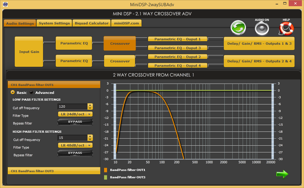
Crossover filters used for subwoofer
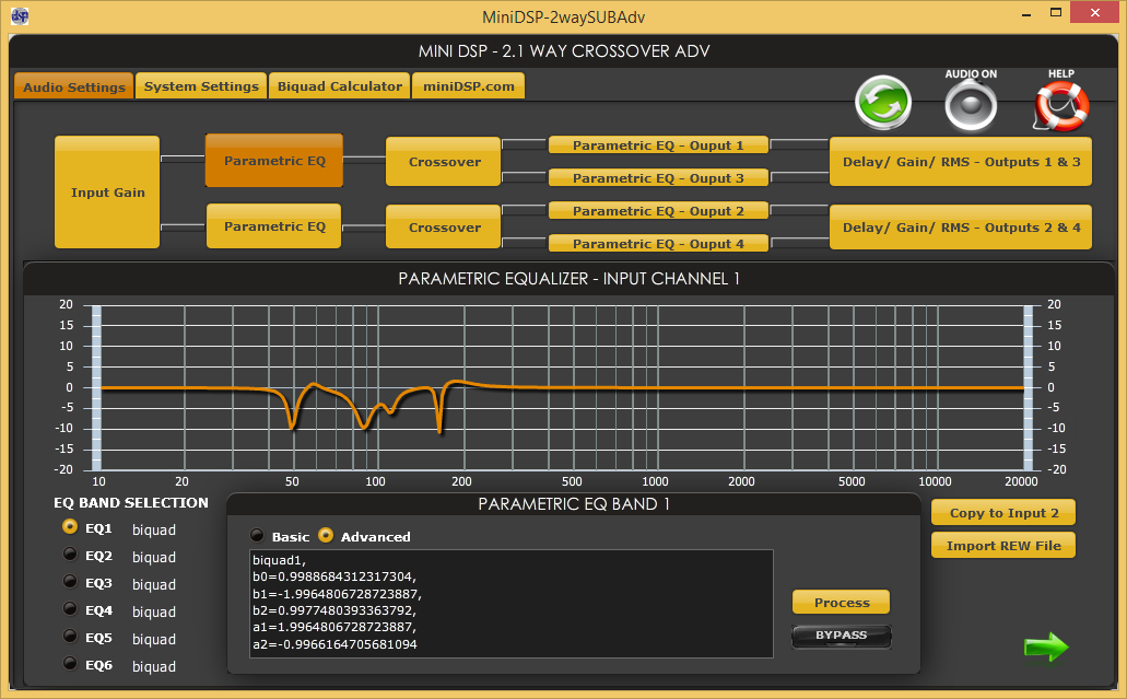
Biquad filter coefficients imported from REW to correct frequency response spikes caused by room acoustics
In order to do these room correction measurements, you need to have a measurement microphone with flat or known frequency response. You cannot just use any microphone. There are plenty of possibilities but the easiest and probably cheapest complete solution is miniDSP’s own UMIK-1 USB-microphone. Typically microphones require preamplifiers with phantom power supplies but this just plugs to USB and comes with a calibration file. REW even recognises this mic and asks for the calibration file. See miniDSP website for instructions how to perform the measurements and filter programming.
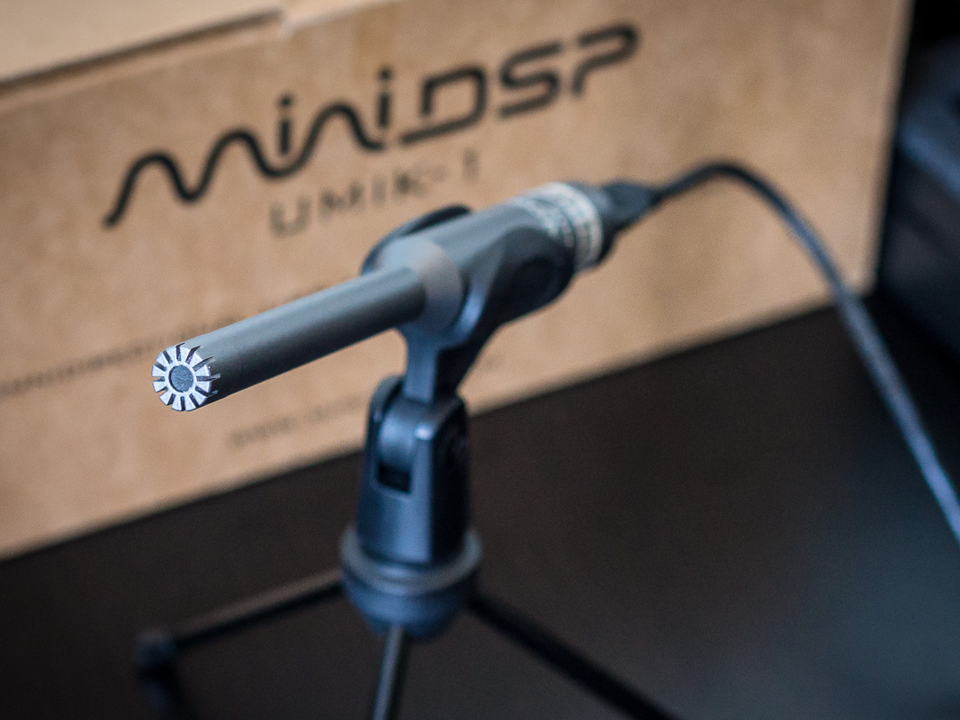
UMIK-1 USB measurement microphone
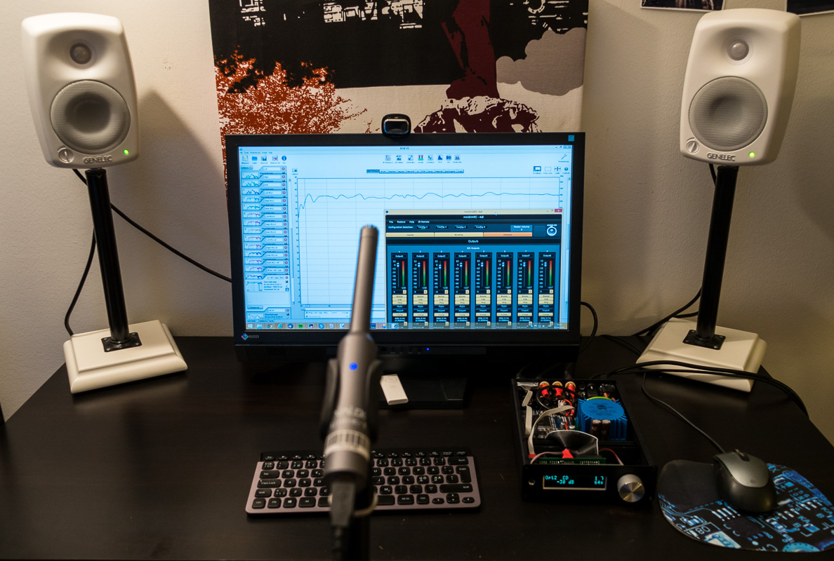
Old photo of UMIK-1 in use with REW and DSP (old miniSHARC-based project)
Why not use only miniDSP?
So if miniDSP is a complete solution, why see the effort of designing a motherboard for it? MiniDSP has analog inputs and outputs so it must be used with line-level analog signals – between preamplifier/DAC and power amplifier. This means volume control is likely going to be before miniDSP, meaning you would actually use it with highly attenuated low-level analog signals. In practice this means lots of lost dynamic range and poor SNR. DSP is a Digital Signal Processor, everything is digital, it should always be before DAC but this is not possibly in all systems and not at all with this miniDSP board. Why would you have your nice and expensive DAC, then use miniDSP’s dirt-cheap on-chip AD-converter and another DA-converter?
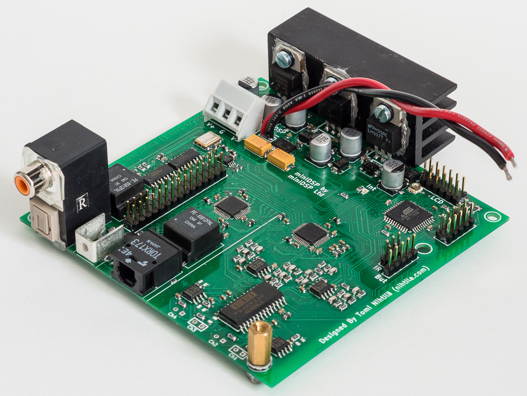
My miniDSP-preamp board places the DSP between digital inputs and DAC and throws in an analog volume control.
DAC-preamp board for miniDSP
The board is a DAC-preamplifier containing digital inputs, sample rate converter (SRC), DAC, and volume control. MiniDSP is placed between SRC and DAC. SRC is required because miniDSP only works with 48 kHz sample rate – DSPs typically operate with fixed sample rate. Therefore, while the board accepts higher sample rates they are all converted to 48 kHz which is typical to most DSP solutions although some may have higher internal fixed rate.
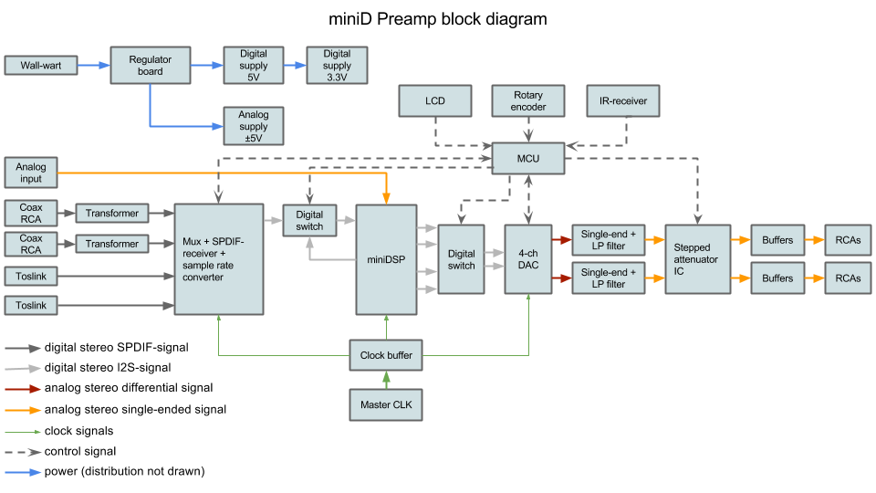
Block diagram below gives an idea of the system. This is from my older version, now LCD has been replaced with OLED.
Design starting point
MiniDSP is basically a black box system as I cannot communicate with it and do not have schematics, only interface. Starting point for the design was:
- miniDSP works with 12.288 MHz master clock (MCLK); it’s own oscillator can be used or clock can be provided externally
- Use external MCLK on my board to provide MCLK to miniDSP, SRC, and DAC; thus everything will be in sync
- Input I2S port is slave and output I2S is master; therefore, it has two clock domains and separate bit clock and word clock for input and output
- SRC will be I2S master and DAC I2S slave
- Sample rate is fixed 48 kHz
- Sample rate converter must be used before miniDSP to support wide range of sample rates
- There are four output channel pairs: two pairs used for the four DSP channels, ADC output, and unprocessed output
- miniDSP’s analog input can be used by looping ADC output back to input
- DSP bypass function can be performed by using the unprocessed output
I have to say I had some confusion with the abovementioned features and thus schematics have some bugs and wrong signal naming.
Basically all the functionality will be provided by microcontroller firmware as SRC and DAC require SPI or I2C control and user interface is software-based.
Schematics
Schematics of the preamp board can be seen as pdf here or as pics below. It is drawn with KiCad and has hierarchical sheets. First page is top level and blocks labeled “Sheet: name” are shown on following pages. Pin-like connections in blocks are hierarchical labels going between hierarchical levels or pages. Power labels are global throughout the document.

Power supply and connections
Power supply of miniD Preamp board is simple LM317/337-regulator circuit providing ±5 V for analog parts and 5 V with 7805 and 3.3 V with TPS70251 for digital parts. I use only 5 V for opamps so that I could use the same supplies for PGA4311, and at some point I powered also miniDSP from 5 V. But it has wider input voltage range and is now powered before this board.
In the same enclosure is a SimplePSU3 voltage regulator board providing dual supply from simple wall-wart type AC-adapter using half-wave dual rectifier circuit and LM317/337 pre-regulators.
High-quality oscillator is used to provide master clock via buffer (CDCV304) for SRC and DAC but also for miniDSP.
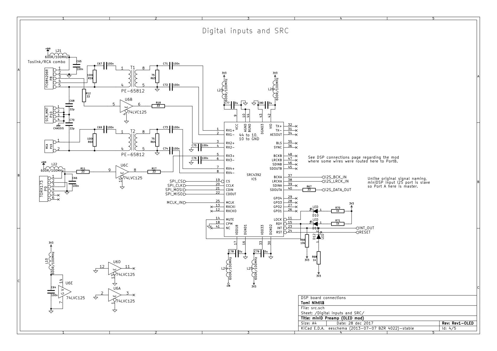
Digital inputs and SRC
TI SRC4392 sample rate converter with S/PDIF receiver is the heart of the input side. It is a very versatile IC providing plenty of routing options and features from which I am only using few. Digital inputs are connected to four inputs of internal multiplexer of the SRC. Isolation transformers are used for electrical inputs. SRC uses master clock and internal phase-locked loop to lock into the incoming digital SPDIF-signal which is decoded into I2S audio. SRC has two I2S-ports and port A is used for connection to miniDSP input. Internal sample-rate converter is used if input sample rate is not 48 kHz which is required by the miniDSP. After setup at startup everything in this IC works automatically.
I made a mistake in the schematics regarding looping the analog input. This is now wired to port B of SRC4392. See Modification section for more information.
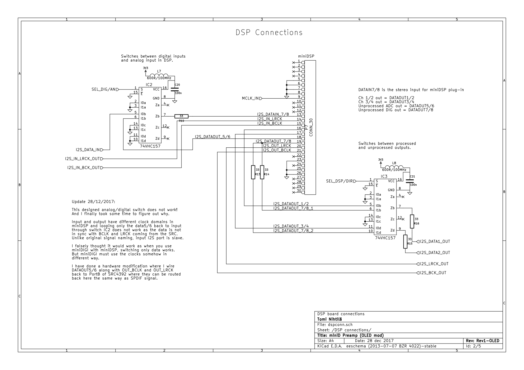
DSP connections
There are extra routing options around miniDSP connector. The switch after the DSP selects if processed or unprocessed signal is used – a DSP-bypass switch. The first switch was supposed to select between analog and digital input but this does not work like that. See Modifications for more information.
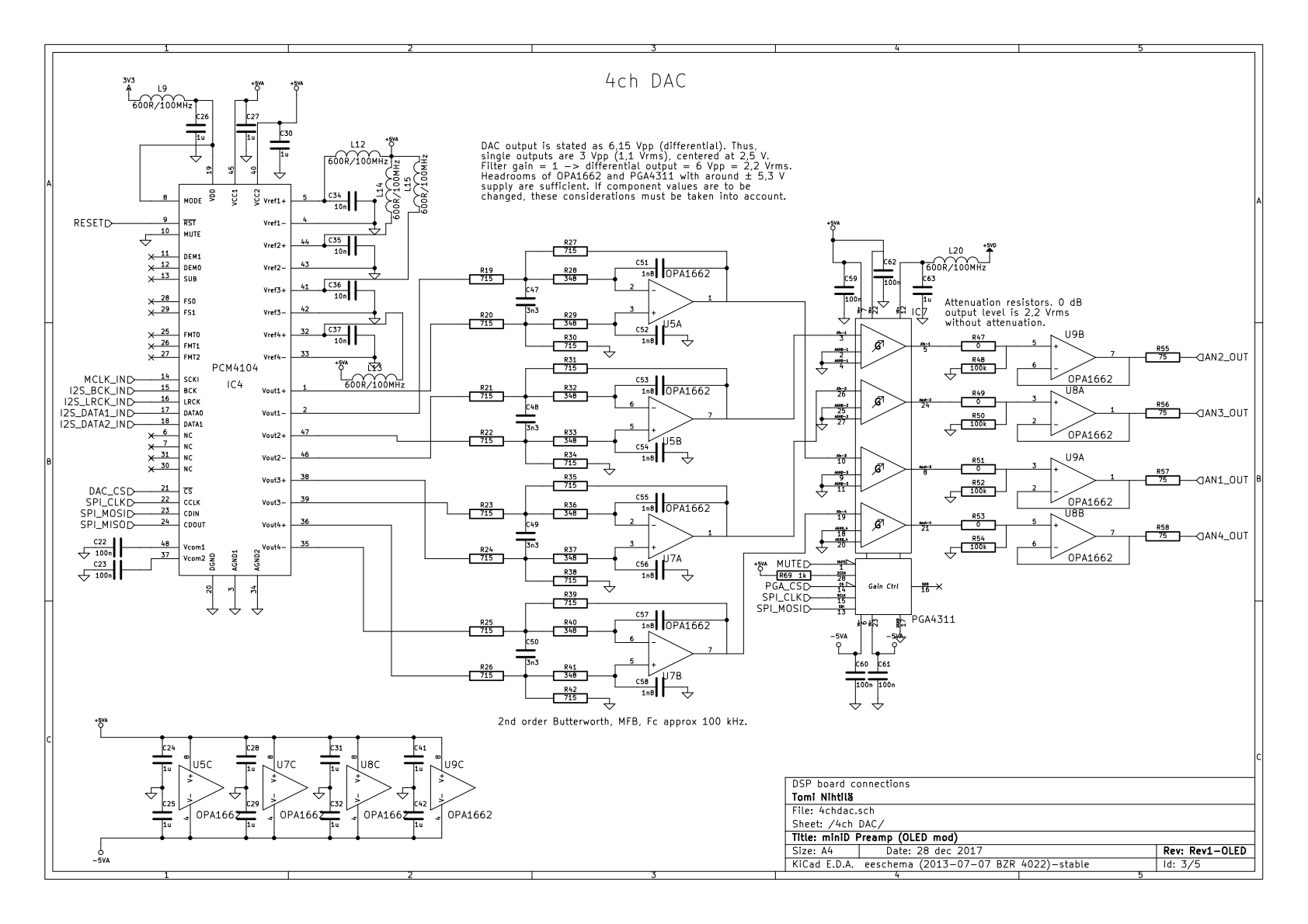
DAC, analog stage, and volume control
Analog section consists of 4-channel TI PCM4104 DA-converter followed by 2nd order Butterworth multi-feedback low-pass filters. The filter circuit is based on the datasheet except I omitted big (electrolytic) DC-block capacitors. PGA4311 stepped attenuator works as volume control after the filters, followed by output buffers.
Due to lack of those DC-blocking caps there are few millivolts of DC at outputs! But for me this is not a problem. However, with analog input there is bigger DC issue that is caused by miniDSP, see Measurements section.
Note that new firmware has an option to use DAC’s digital volume control so PGA4311 is not mandatory anymore.
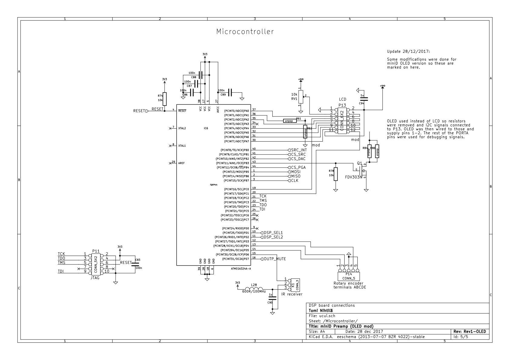
Microcontroller control circuit
Microcontroller here is ATmega324A with connectors to programmer, OLED, rotary encoder and IR-receiver. I didn’t include crystal but it would have made the time-sensitive IR-remote control operation slightly easier.
Modifications
As is written in the schematics, the ADC signal looping did not work as I thought. I got confused as in my previous configuration with miniDSP miniDIGI board it works only by looping the data signal, also shown in miniDIGI user manual. However, as miniDSP input and output have their own clock domains, looping the data from output to input is not enough but bit clock and word clock are needed as well. Therefore, bit clock, word clock, and ADC data from miniDSP output were wired into SRC4392 port B, as shown below, and then re-routed back to input using the SRC.
The two gray wires going from microcontroller to pinheader are for OLED. These are I2C lines wired to pinheader for easier connectivity.

Three orange wires connected from miniDSP output to SRC to make analog input work. Two gray wires are for OLED.
Another small modification is bending (as there was no space to cut) one pin in miniDSP connector. This is due to misinformation in one of their documents. And I cannot believe they still have not corrected it 5 years later, I have even let them know about it!
In miniDSP user manual page 40 it says pin 23 is GND but in the datasheet it says it is 5 V from USB – which it is. So this means direct short if this pin is GND as in my board!
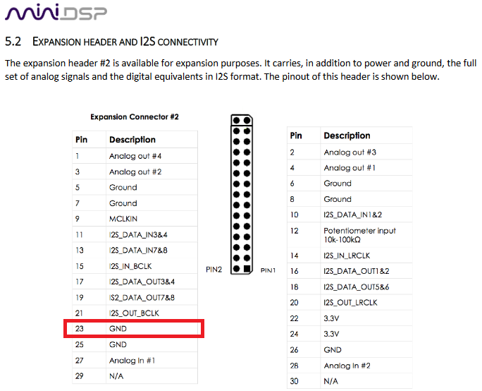
miniDSP pinout in user manual
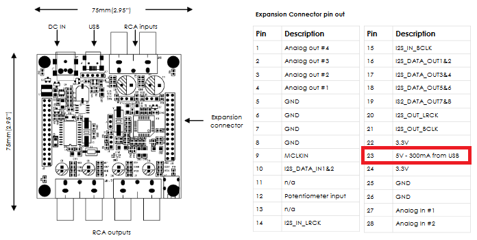
miniDSP pinout in datasheet
It is also worth noting how poor the pin allocation of this connector is overall. There is only few ground pins and no ground pins next to clocks. Sorry miniDSP but this is very bad practice.
Firmware
I compeltely re-wrote the firmware in December 2017 when putting the device in a new enclosure and replacing broken LCD with OLED. This project had been waiting for almost a year. And it was not a quick thing to do. I am not going into details of the firmware here as it would take too much time. However, I made a short video showing the functionality and the code is for you to download and modify based on what you have seen. It is not the simplest firmware and I am not a professional firmware developer but there should be quite a lot of comments.
Features are as follows:
- Volume, from mute to set limit (hardware limit is 31.5 dB for PGA4311 or 0dB for PCM4104)
- Volume control can be changed between analog PGA4311 or digital PCM4101 DAC
- Input selector (short push); two optical, two coaxial, one analog
- Blinks input name if no digital signal locked
- When locked, briefly shows input sample rate (although this will be sample rate converted)
- Infra-red remote controllable with NEC-compatible remote control
- Can learn the codes
- Settings stored in EEPROM
- Menu access by long push, with following settings
- DSP bypass
- Output 2 mute
- Output 2 offset
- Volume control analog/digital
- Use optical2/coaxial2/analog (can disable these inputs)
- Startup volume
- Volume (software) limit
- Offset volume for each input
- Balance for output 1 and output 2 separately
- Startup delay (to unmute)
- Sample rate converter filter group delay (digital filter setting in SRC)
- De-emphasis filter setting
- Learn IR commands
If I may say, quite packed with features! At the moment I use small old Apple remote for IR control. There are some small changes I may need to make to the firmware but overall it is working really well. For once I tried to do proper firmware debugging and monitoring and not just finish when it was somehow working. I used my oscilloscope’s logic analyser and AVR in-circuit debugger to get at least some kind of understanding what is happening in there.
Code files can be downloaded here. It is divided into few files but there is no fancy parameter passing between the blocks but global structures are used. Otherwise all code is mine except I use u8g2 library for the OLED.
Below is a video showing the software functionality:
Enclosure
Enclosure frame is from eBay and front and back panels are from Schaeffer AG where you can easily order custom aluminium panels using their simple CAD software. I have used them few times already. Quality is good although the edges look a bit unfinished. Still superb and easy (if not cheap) way to get nice looking enclosures for DIY.
One slight whining is the direction of aluminium brushing marks though – they are vertical but are usually horizontal! So if you order from them, mention this in comments as I did in my next order and got them the way I wanted.
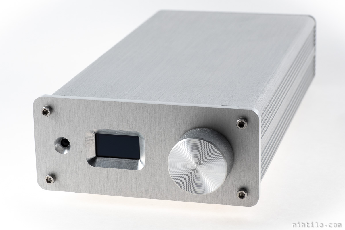
5 mm thick front panel with carvings for OLED and IR and holes for rotary encoder and mounting.
Back panel is thin aluminium with filled carvings as prints. Channel numbers refer to numbering in miniDSP plugin software. Connector placement is not perfect due to slightly cumbersome board stacking and lack of space.
Back panel is thinner 1.5 mm aluminium with prints and connector holes.
Measurements
I did not perform as comprehensive measurements as of H-DAC or some other boards but this was more like a sanity check that my old board does not have any major performance flaws. And I am glad to say it does not. I performed the measurements at my work with Audio Precision APx555 audio analyser. The device was powered with a 12 VAC 1 A wall-wart pictured in one of the photos.
Key figures
Following measurements are done with 0 dBFS signal level and coaxial digital input, unless otherwise mentioned. Measurement bandwidth is 20 kHz. 1 kHz sine was used in single-tone measurements.
- Signal level 2.2 Vrms = 6.8 dBV
- DC offset few mV – scroll down for large DC offset issue using analog input and outputs 1 and 2
- Noise level
- Ch1: -106 dBV (A-weighted -108 dBV)
- Ch2: -105 dBV (A-weighted -107 dBV)
- Ch3: -105 dBV (A-weighted -107 dBV)
- Ch4: -105 dBV (A-weighted -107 dBV)
- Noise level, analog input: -91 dBV (A-weighted -93 dBV)
- SNR A-weighted: 114 dB (weakest channel)
- Sample rates up to 192 kHz are accepted and show similar performance (signal is converted to 48 kHz)
- THD+N Ratio (analog volume control, digital control has better distortion performance, see graphs below)
- Ch1: 0.0028 %
- Ch2: 0.0036 %
- Ch3: 0.0037 %
- Ch4: 0.0037 %
- Current and power consumption (using DC bench PSU and miniDSP powered from positive rail):
- Supplies ± 8 V
- +8 V: 258 mA (2.06 W)
- -8 V: 47 mA (0.38 W)
- Supplies ± 12 V (just to see how much current changes, the board has 5 V regulators)
- +12 V: 242 mA (2.91 W)
- -12 V: 50 mA (0.60 W)
- Supplies ± 8 V
Frequency response
There is slight roll-off at high frequencies which is likely from the analog output filter. Although its corner frequency is around 100 kHz, this small attenuation can already be present at the end of audio band.

Frequency response (note the scale)
Crosstalk
I only measured crosstalk within one channel pair as a sanity check, not all combinations. No surprises here. Signal level is 0dBV so the dBV number on Y-axis is the crosstalk figure.
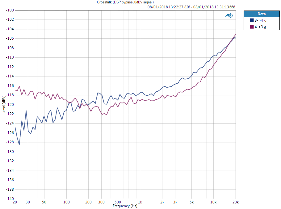
Crosstalk between channels 3 and 4 (the main channel pair)
THD+N vs. amplitude
Below is THD+N level vs. amplitude, also showing noise floor, and THD+N ratio vs. amplitude. Amplitude here is generator amplitude, meaning 0 dBFS is 2.2 Vrms.
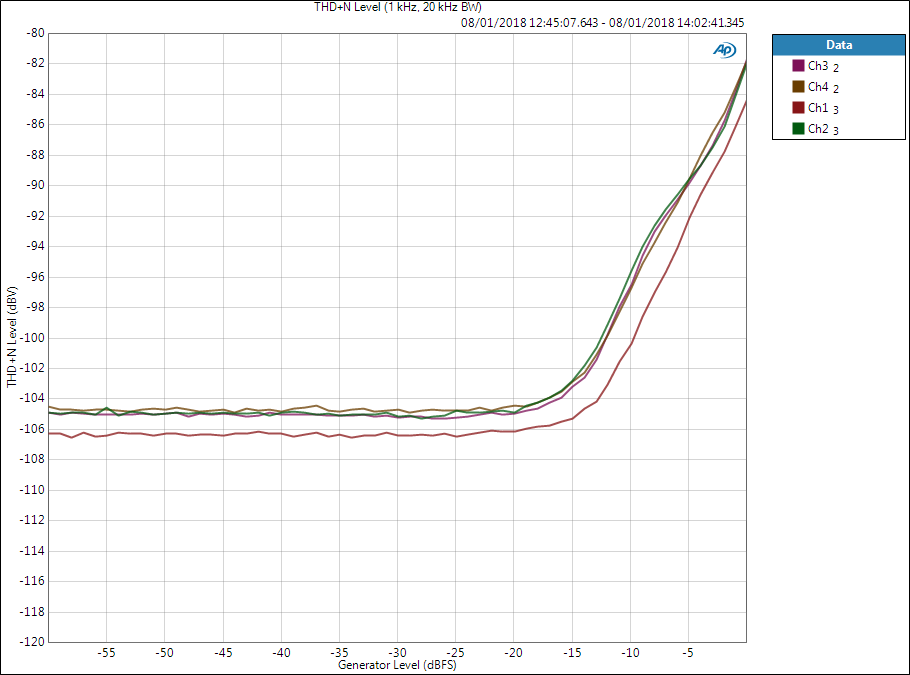
THD+N vs. amplitude level
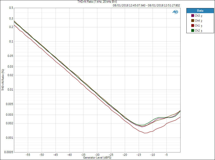
THD+N ratio vs. amplitude
While noise level and therefore SNR is excellent, distortion close to maximum level increases a bit more than expected.
As I was suspecting this increase in distortion may be due to low supply voltage for operational amplifiers (±5 V), I made a comparison between analog and digital volume control. So bear with me, now we will dive a bit deeper… I advise to have the schematics at hand when going through this.
Digital vs. analog volume control performance
When I designed this board few years ago, I had this fear of digital volume controls – which is a common misconception in HiFi. So the idea was to operate DAC at maximum level and then use PGA4311 stepped attenuator for analog volume control. As PGA4311 wants ±5 V supplies and I did not want to have loads of supplies in this design, I opted for ±5 V also for opamps. This also made it possible to use an AC wall-wart to power up the device.
But is the low opamp supply responsible for the peformance degradation at high signal levels? To test this I made THD+N measurements volume set to -10 dB with both analog and digital volume control. Only channels 3 and 4 are included.
Below is THD+N with -10 dB using PGA4311. In an ideal case everything would come down 10 dB but in fact we hit the system noise floor of around -110.5 dBV. However, distortion comes down 10 dB. This means that we actually lose 4.5 dB in noise level (as the noise comes down 5.5 dB instead of 10 dB) but the difference remains the same in higher levels where distortion is dominant. This can be clearly seen in THD+N ratio graph below where the ratio is identical at high levels. Therefore, we can state that distortion is present already before the PGA4311.
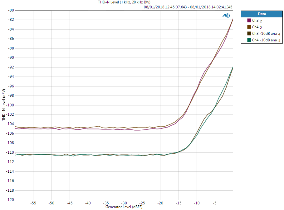
THD+N level, full-scale signal vs. -10 dB using analog volume
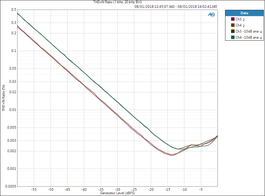
THD+N level, full-scale signal vs. -10 dB using analog volume
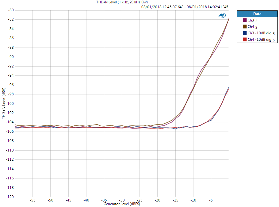
Ok, next digital volume control. In this case PGA4311 is set to 0 dB and digital attenuation of DAC chip is used. Same graphs as above, -10 dB (digital) attenuation compared to original 0 dB level.
Below we see the known phenomenon for digital volume control – noise floor remains constant. This is because theoretically it is defined by the quantization noise, in practice the output stage of the DAC. Anyway, there is no resistance division attenuating the noise. But look at the distortion – it attenuates over 14 dB at full-scale signal. This is clear in THD+N ratio graph – THD+N ratio is better at very high signal levels.
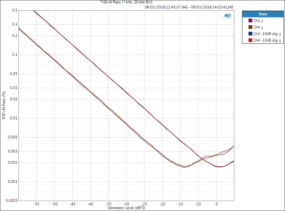
What does this all mean then? Clearly dominant part of the distortion comes from the opamp filter circuits between DAC and PGA4311. So even when PGA4311 volume is turned down, this part of the circuits operates at maximum level and add distortion. Briefly said, if I would re-design the circuit I would just leave PGA4311 out completely and use DAC for volume control. The board would get a lot simpler and while THD+N ratio would degrade at lower signal levels due to fixed noise floor, the distortion would actually be better. While I have the PGA4311 there, I would get the optimal result by adding a bit of attenuation in the DAC so that filter circuit does not distort as much, and then use the PGA4311. I may do that change in the firmware one day.
In general, the best result can be often achieved in combination of digital and analog volume control. For example, use resistors and jumper links to define approximate maximum signal level and then use digital volume control.
Yes, this was diving in the deeper end but good lesson regarding analog and digital volume control. When the digital chip provides noise floor close to the analog noise floor of the design, there is no need to even dream about analog volume control anymore. It just adds complexity and cost.
DC offset issue
Although I got the analog input to work with the mod, there is a serious DC offset issue that is somehow caused by the miniDSP board. This may lead to volts of DC at the output! This issue is present when using analog input with the loopback mod, if analog input is selected in plugin there is no offset.
If preamp is set to 0dB, meaning full-scale signal and no signal is played back, there is 3.13 V DC at output channels 1 and 2. This is somewhat the whole 3.3 V supply. However, when signal is played back, this DC seem to get lower so there is no huge distortion.
When looking at the idle I2S signal coming from the DSP, it shows values in the order of 0x7Fxxxx so it really seems this near full-scale DC is present in the digital signal.
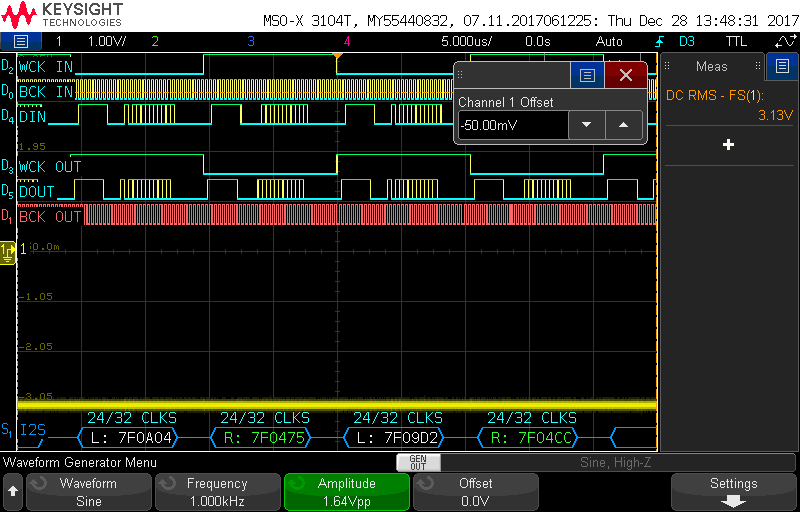
I2S stream decoded in oscilloscope showing near full-scale offset
Furthermore, to conclude this DC comes from the DSP or its ADC, muting output or using high-pass filter removes the offset.
I did not try to get rid of it as I probably cannot do anything to it. Just need to remember if using outputs 1 and 2 (which is the “second” output pair). If I will use those, it will likely be for a subwoofer whose subsonic filter will remove the offset anyway.
Conclusion
After writing completely new firmware and upgrading the display and enclosure now in December 2017 I am quite happy with this! Sure the board is not up to my today’s standards but it works well and measures reasonable well also. I spend a lot of time re-writing the software and having a proper debugging and trying to understand really what is happening in there. Although I made measurements quite quickly the analog vs. digital volume control was also good exercise.
I understand this is not the easiest project description to follow as there are many parts. However, if you are familiar with digital audio it should be understandable at least what is going on. For other DIYers planning to go a bit deeper with miniDSP, I hope you got some valuable information. At least try to avoid the mistakes I made. Feel free to comment and ask questions.

miniD preamp on my current desktop setup with other DIY kit
Version history
Device
- Mid 2014 Initial version
- End 2017 OLED version
This page
- 1.12.2014 Initial version
- 8.1.2018 OLED version