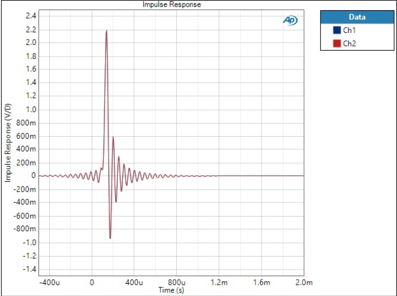
This post delves into digital filters in AK4490 and AK4493 DACs used in W-DAC boards and provides extensive measurement results of the filters in time and frequency domain. This is not only relevant to these specific DAC chips and filters but general information on DAC digital filters from audio perspective. This is a practical approach – no poles, zeros, or formulas but lots of plots.
Learning
I bought a second hand M-DAC to have a well-known commercial reference in terms of measurements and sound. Obviously I needed to open it and see what’s inside. This is not a detailed reverse-engineering report but a glance inside with plenty of photos. Measurements are coming later.
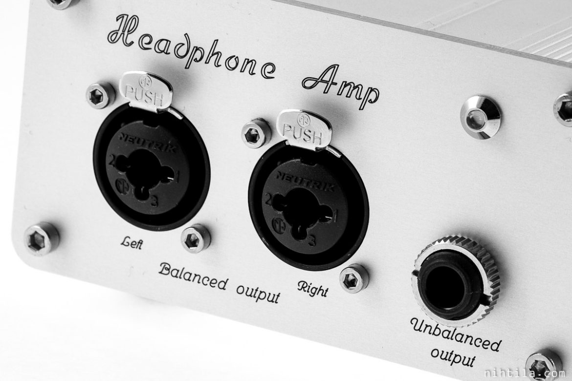
- In balanced connection both speakers are individually connected to amplifier using two wires for each channel
- Crosstalk can be improved by tens of dB by using balanced interconnection
- Common-impedance coupling seriously limits crosstalk in conventional unbalanced headphones
- Balanced output can be easily and cost-effectively added on designs; inverted signal is not required
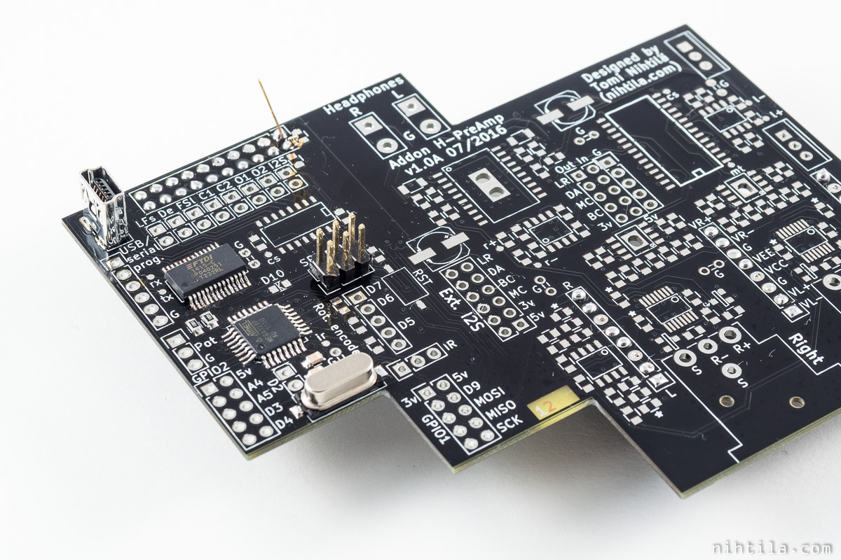
I have stated some of my boards as “Arduino-compatible” as many other DIY and commercial electronics you can find nowadays. Simply put it means that you can develop Arduino programs (sketches) for that board with the Arduino IDE. Here are some information and references how to make a board Arduino compatible and what it means.
- Expresses “leaking” between channels; it is measured by driving a stimulus signal in one channel while listening to the other.
- Crosstalk is expressed as a ratio between the quiet undriven channel and the stimulus in the driven channel, and given in decibels.
- Presents the unwanted part of signal – something that was not put there and should not be there.
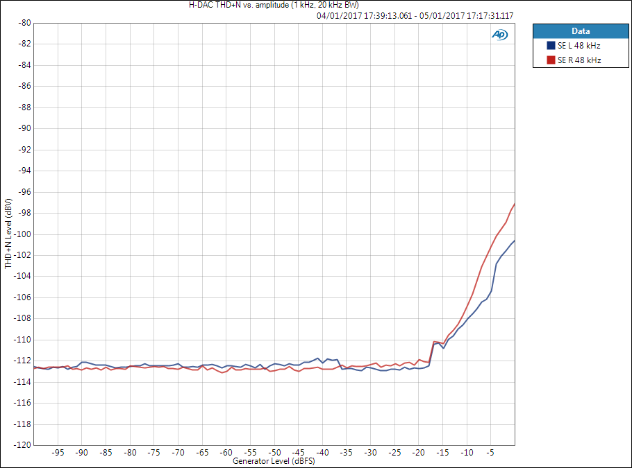
- THD+N vs. amplitude graph is important as it reveals SNR, dynamic range, and THD+N ratio; all are expressed as ratio compared to a specified signal level.
- The difference between THD+N level and THD+N ratio must be understood.
- Signal level, signal frequency, and measurement bandwidth must be known (or guessed) when analysing results.
- SNR is a ratio of two measurements, level and noise measurements, expressed in dB.
- Signal level, measurement bandwidth, and weighting filter must be defined.
- Dynamic range is like SNR but noise is measured in the presence of small signal; results should be the same.
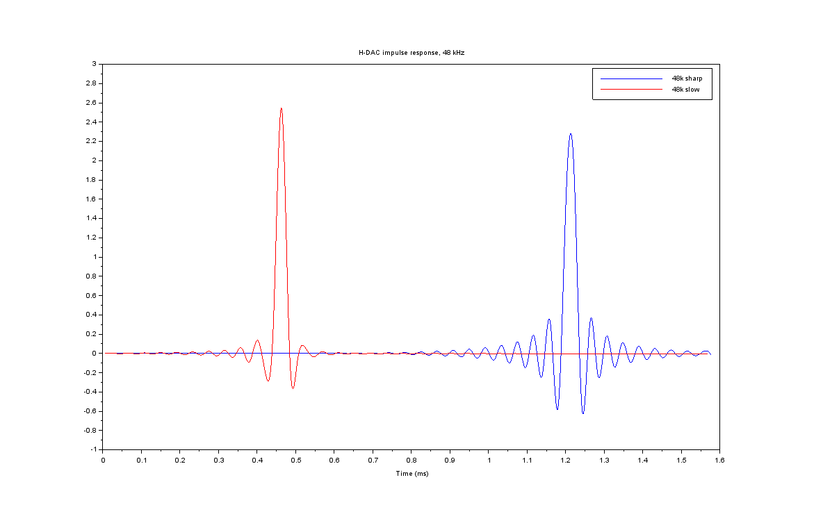
Many DAC chips and devices using those chip have user selectable options for digital filter response to fine-tune tonal characteristics. I will take PCM1794A used on H-DAC as an example and see what effects these filter types have on impulse and frequency responses. This is just scratching the surface of the topic by briefly introducing some technical effects that can be measured. Tonal characteristics are not discussed here; those are highly subjective and a topic of another post (or debate).
