
- Three linearly regulated voltage outputs
- One dual supply for analog voltage supply
- One single supply for digital voltage supply
- Separate grounds
- Fuses, rectifier bridges, filter capacitors, and regulator circuits
- 2x LM317, LM337 (or any pin-compatible)
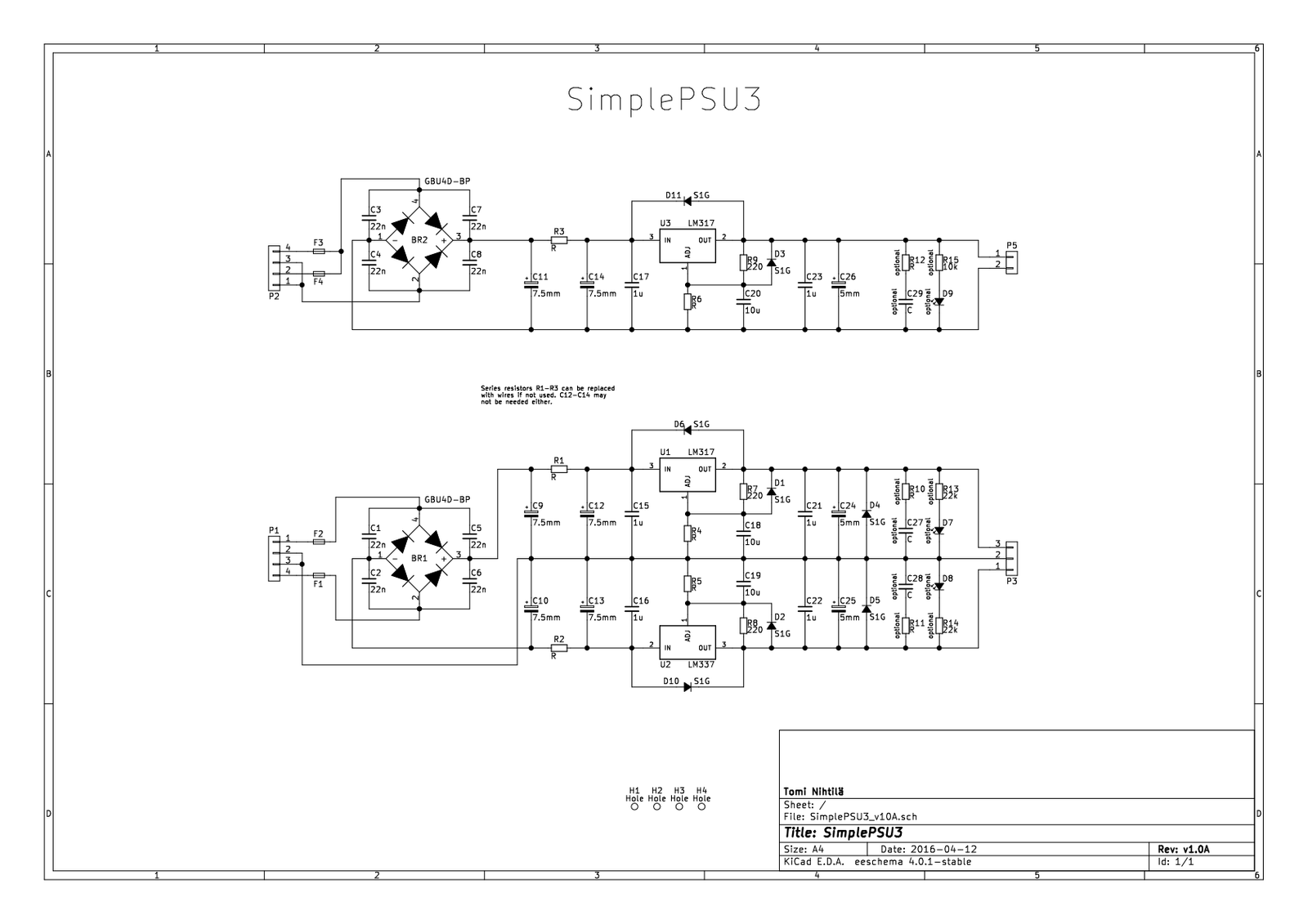
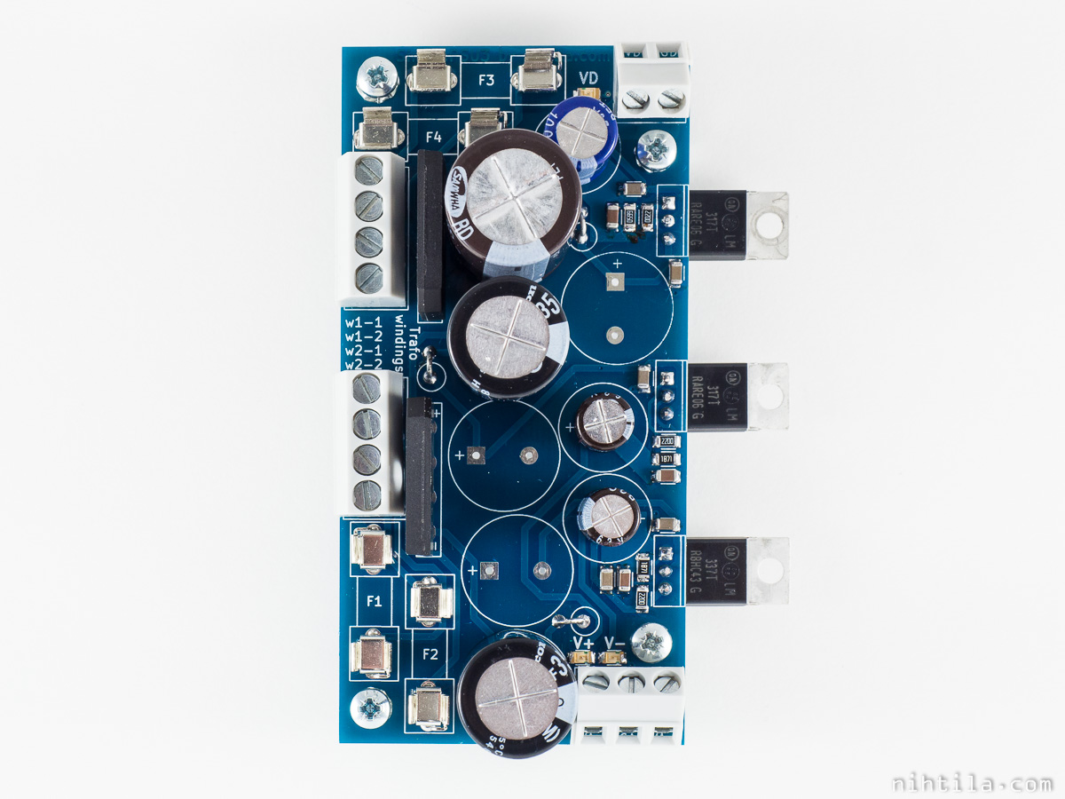
SimplePSU3 contains three simple 3-pin adjustable regulator circuits. Its one dual (analog) supply and one single (digital) supply suits especially well mixed signal audio circuits. Regulators are placed on the edge of the board for mounting on heatsink or chassis.
Design and schematics
Design is typical LM317/LM337 circuit with few optional components.
Fuses are on board in case transformer is wired to SimplePSU3 (primary fuse must still be used!), followed by rectifier bridges with capacitors to reduce diode switching noise. Filtering stage consists of two electrolytics per rail and series resistor in between. Resistor can be replaced with wire and the second electrolytic may not be necessary. Regulator circuits are typical designs, followed by more (small) capacitors and optional snubber and LED circuits at the output. Use the components that are required in your application.
Note that if SimplePSU3 is used with DualTrafoBoard, it is not necessary to use fuses, rectifier bridges, and all filter capacitors in both boards. For example, use the ones on DualTrafoBoard and connect wires from fuse footprints to series resistor footprints (F2 -> R1, F1 -> R2, and F3/F4 -> R3) on SimplePSU3 board; just ensure that voltage polarities are correct.
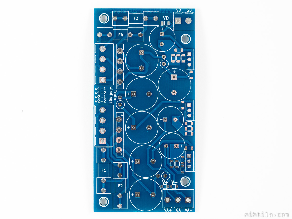
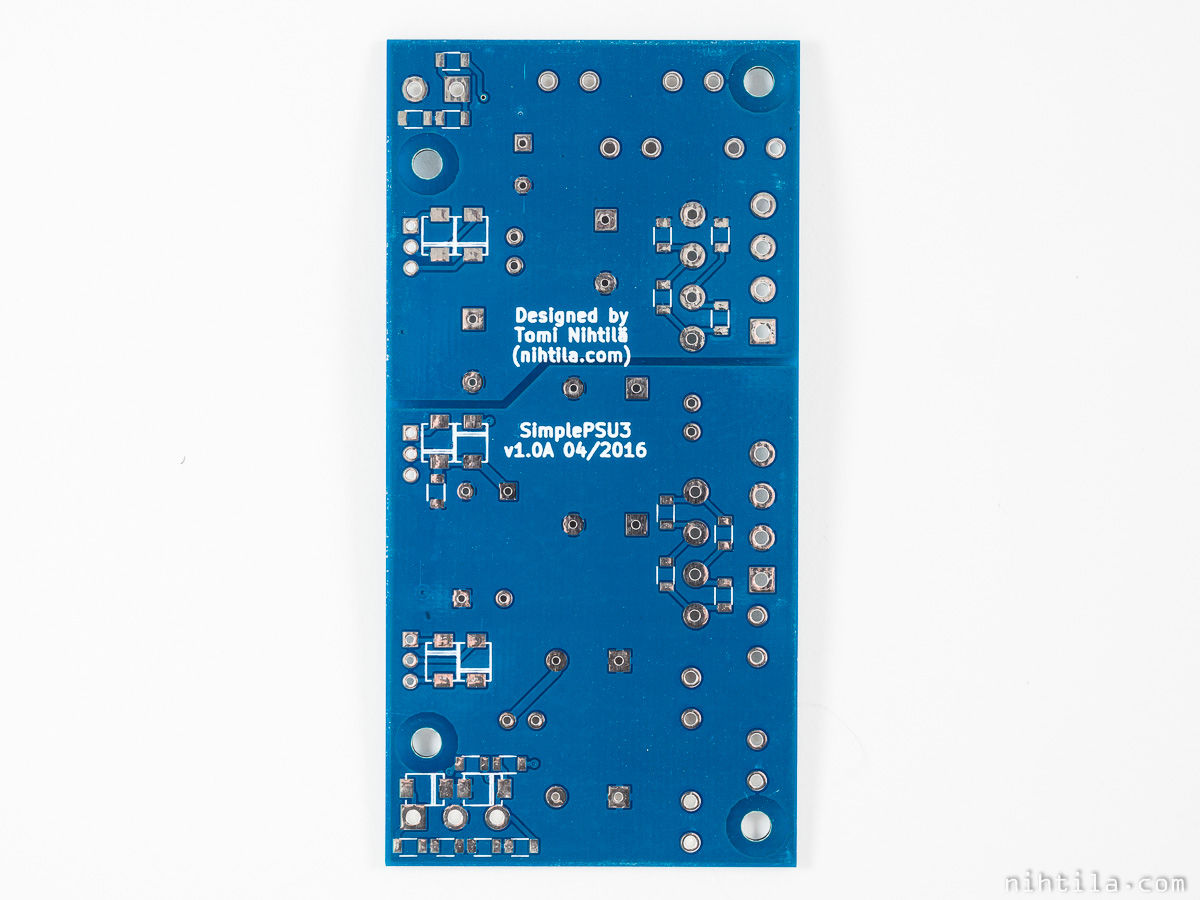
Layout and components
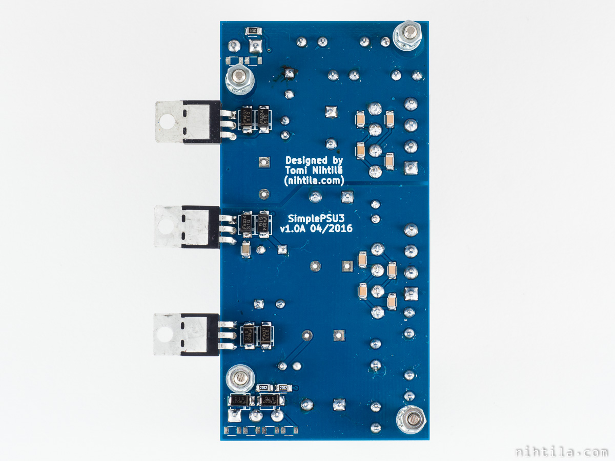
PCB is 5×10 cm and 2 layers. Larger components are through-hole and SMDs in 1206 case.
Note that rectifier bridge holes are slightly too small for the shown bridge model. Small metal pieces may get off when pushing the component legs through the holes. Ensure these pieces cannot cause any shorts.
Also ensure that the chosen fuse holder models cannot touch each other (see photos).
Measurements and tests
I have only populated one board and tried that it is functional – no further tests or measurements are done. I may do some proper power supply measurements at later time. However, it is very typical regulator circuit and there should be no surprises. Electrical performance should follow the chosen regulator model.
Files
v1.0A files in PDF
Version history
Schematics and PCB
- v1.0A Initial version
- Possible changes for next version
- Slightly enlarge rectifier bridge, regulator, and electrolytic capacitor holes
- Bypassing fuse and rectifier; add extra pads and draw a line on silk screen
- Add reference designators on silk screen?
- Add some protective components such as TVSs
This page
- 2.1.2017 Initial version