
- High performance; H-DAC + H-Filter system performance measured with fixed resistors:
- SNR: 119 dB (A-weighted)
- THD+N ratio (1 kHz / 2 Vrms): -100 dB
- Crosstalk: -112 dB at 1 kHz, -100 dB at 10 kHz
- I/V-stage, filters, output stage, and opamps implemented with through-hole components for easy experimentations
- Balanced outputs (XLR) on-board, uses unbalanced connectors (RCA) on H-DAC board
- Potentiometer for volume control to transform H-DAC into preamplifier, or resistors for fixed output level
- Takes voltage supplies and audio signals directly from H-DAC via pinheaders
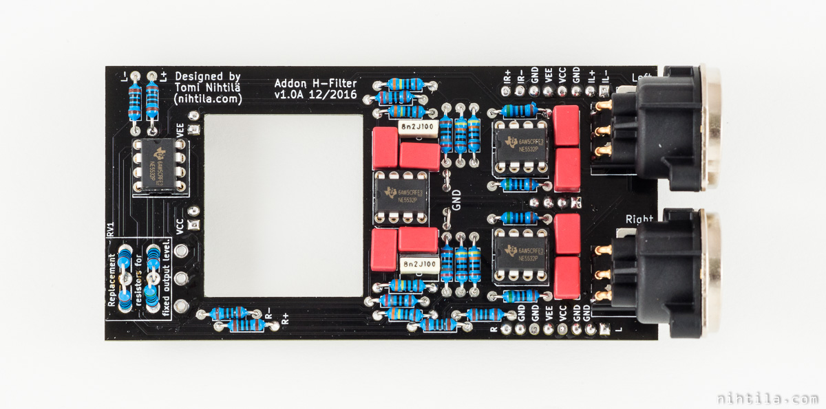
- 5×10 cm 2-layer PCB, through hole resistors and capacitors, placeholders for DIP8 sockets for opamps
Addon H-Filter is a simple filter and output addon for H-DAC with a possibility for a potentiometer to transform H-DAC into a preamplifier. In contrast with other designs of mine, it has been designed with through-hole components to allow easy experimentations with opamps and passive components. It offers high performance with low BOM cost and easy solderability.
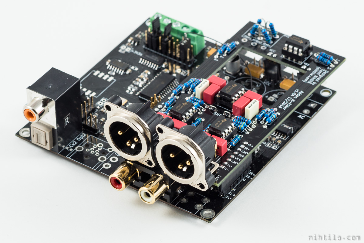
Addon H-Filter stacked on H-DAC.
Design and schematics
Addon H-Filter is stacked on pinheaders of H-DAC, connecting to current outputs of the DAC chip, and bringing balanced outputs and also preamplifier functionality if potentiometer is populated. XLR-connectors for differential signals are on board and single-ended signals are routed back to the H-DAC board as in Addon BalOut. Schematics until the potentiometer are exactly the same as in H-DAC. See H-DAC page for more detailed explanation and link for the LTSpice file for filter simulation.
When H-Filter is used, analog output stage of H-DAC must not be used as otherwise DAC output current will be split.

Volume control
Volume control in balanced design can be tricky to implement if both hot and cold signals are to be controlled. One option is to use 4-channel volume control IC as in Addon H-PreAmp. While software-operated volume control brings possibility for remote control and all fancy features, it brings the system complexity and cost to a completely new level. Another option is to handle the signal internally as single-ended, use normal stereo potentiometer, and have balanced drivers at the outputs. This may not feel elegant, especially if the DAC already has differential output.
More creative and simpler solution can be achieved when realising the nature of balanced interconnects and ground references. Excellent and easy to understand reference material are Bruno Putzeys The G Word paper, where this volume control idea is taken, and the ones listed at the end of this page. Briefly the main points are that balancing means impedance balance which has nothing to do with having mirrored signal in hot and cold wires, and that even so called single-ended signal is differential signal – the reference is just ground (which is often very confusing “concept” as is very nicely explained by Mr Putzeys). When this ground reference is treated accordingly we can effectively have differential balanced interconnection.
How the above is seen in Addon H-Filter? The output of U3 is single-ended but can be considered as differential signal between the opamp output and ground reference point JP1/JP2. When the ground trace is only used for return path for the audio signal, they form differential balanced connection. JP1/JP2 are used so that schematics/layout software distinguish the net from ground. U4 amplifies the signal between U3 output and this same ground reference point. Furthermore, balanced output is also the signal between U4 output and this one ground reference point, fed through serial resistors creating the actual balanced interconnection. How “good” a balanced interconnection is, is a matter of impedance balance; in this case how similar the ground series resistor and output series resistor plus opamp output impedance are.
This idea is very clever in its simplicity and significantly reduces the cost and complexity of balanced outputs. It does not have the higher voltage swing of mirrored differential outputs but it does have the more important benefit of good common mode rejection and immunity to ground loops when XLR-connectors are properly grounded (avoid “The Pin 1 Problem“).
One disadvantage of this solution is that there is no such thing as maximum volume in this volume control! It just adds more and more gain and eventually will distort the signal so heavily that sine wave becomes square wave. This could be prevented by adding series resistors between U3 and the potentiometer. However, I did not put placeholders as Mr Putzeys was strictly against that in his article but I am not completely sure I agree with everything…
Note that positive/negative outputs of I/V-stage are swapped when connected to next stage as volume control stage U4 inverts the signal.
Components
Components used in the prototype are very basic – some basic 1 % resistors and plastic capacitors. To improve balance, one can match resistor pairs. NE5532 opamps are used but any pinout-compatible is fine. As has been shown in the measurements, potentiometer quality has significant impact on the overall performance.
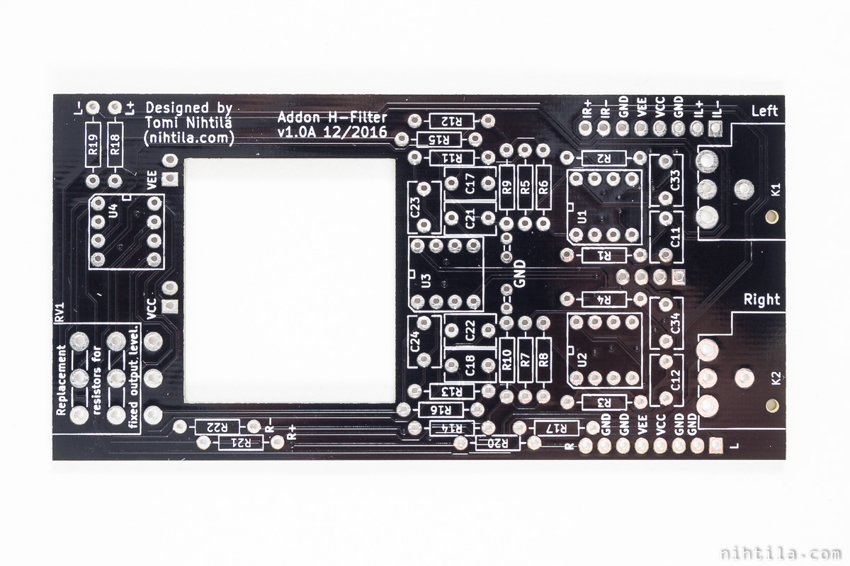
Layout
PCB is simple 2-layer board to follow the simplicity and cost reduction concept. It works relatively well in this as opamp supply voltages are taken from the H-DAC board below. XLR-connectors are taken partly over the edge of the PCB to bring potentiometer slightly farther away but still keep the PCB at 10x5cm due to cost reasons. This allows H-DAC regulators still to be mounted on the bottom of the chassis even if potentiometer is mounted on front panel, when using approximately 12 cm long chassis.
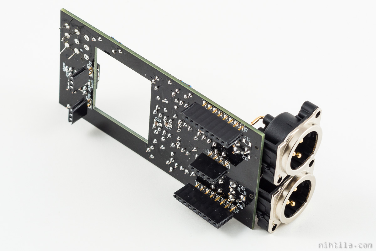
PCB has a large rectangular hole in case large electrolytics and fuse are populated on H-DAC.
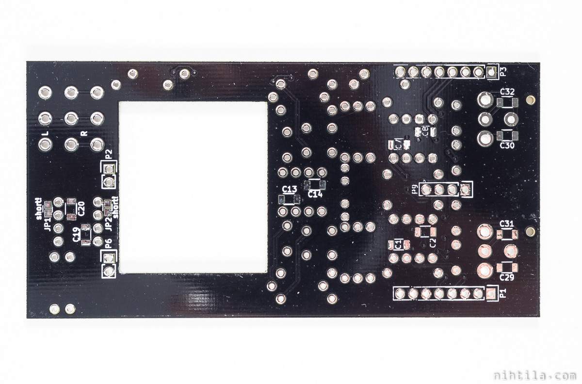
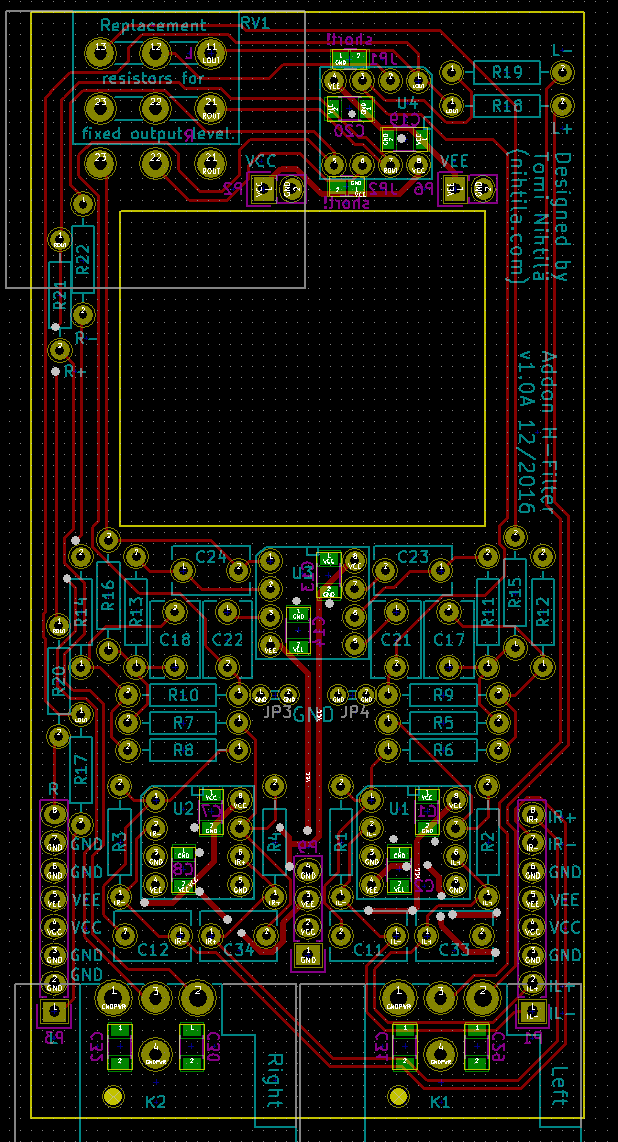
Top layer
Few more notes:
- Pot should not be wired (far) away from the board – mechanical extender is a better solution.
- Use taller pinheaders between H-DAC and Addon H-Filter due to H-DAC RCA connectors (see photo above where pinheaders are soldered with gaps to the board).
- If volume control is not needed, populate resistors for fixed output level.
- If potentiometer is used, it should be good quality – see measurements.
Measurements
Audio measurements are performed with Audio Precision APx585 analyser. Addon H-Filter is measured stacked on H-DAC as it would be used. Both balanced (on H-Filter board) and single-ended (on H-DAC board) have been measured.
The measurements have been performed with cheap potentiometer and with two 560-ohm resistors in place of the potentiometer to show the differences. In both cases output level is adjusted to 2 Vrms. Unfortunately I did not take a photo with the potentiometer populated but it is the longer shaft pot shown on the main photo (the other one is even worse).
Key figures (with fixed resistors), stacked on H-DAC:
- SNR (A-weighted): 119 dB
- A-weighted noise level: -113 dBV (20 kHz bandwidth)
- Signal level: 2 Vrms (6 dBV)
- THD+N ratio: -100 dB
- 0 dBFS / 48 kHz at DAC, 1 kHz / 6 dBV after H-Filter, 20 kHz bandwidth
- Crosstalk: -112 dB at 1 kHz, -100 dB at 10 kHz
- Current consumption (Addon H-Filter only, no signal):
- +12 V: 29 mA
- -12 V: 29 mA
Frequency response
Frequency response with cheap potentiometer is shown below. This pot has approximately 0.35 dB tracking error in the mid position but the other one I tried had a whopping 2 dB error even at this middle position. At low levels the error was even larger.
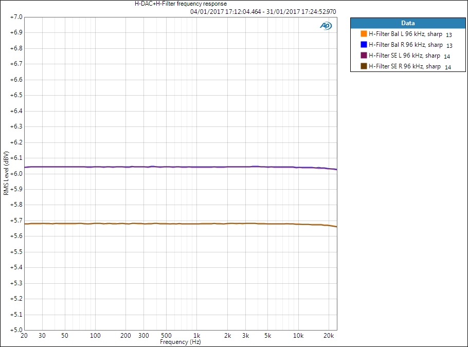
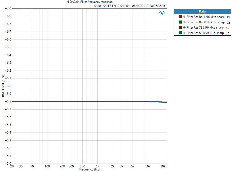
With fixed resistors the response is flawless:
Noise level
Noise level of H-Filter is very good and could be even better with some lower noise opamp. Even with NE5532 we hit non-weighted noise level of -110 dBV.
Significant difference to Addon H-PreAmp is also the behaviour of noise when volume is turned down. When volume is controlled with potentiometer, noise floor gets lower when volume is turned down. This gives some practical THD+N ratio advantage. If volume is controlled digitally, noise floor is fixed despite the volume level. In Addon H-PreAmp measurements I have noticed that PGA4311 is somewhere in between but closer to digital volume control – the noise do get lower by some extend but not much.
THD+N vs. amplitude
Below is THD+N vs. amplitude measured with the cheap potentiometer.
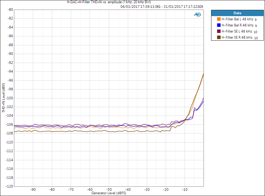
Here below are measurement with fixed resistors in place of the potentiometer. Results are more consistent and show few dB improvement. We still have the distortion difference between left and right channel which has been seen in all PCM1794A circuits and thus is likely a feature of the DAC itself.
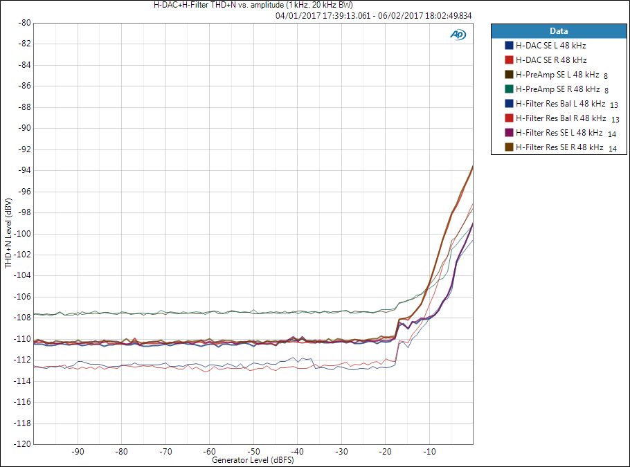
 Below are the above results compared with H-DAC and Addon H-PreAmp results (thin lines). It may not be a surprise that Addon H-Filter is weaker than H-DAC but I was not expecting it to be better than Addon H-PreAmp – and we use NE5532 here. Obviously the simplicity here is advantageous.
THD+N ratio vs. frequency
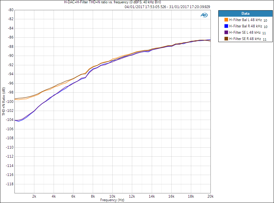
Below are THD+N ratio vs. frequency measurements with 0 dBFS / 2 Vrms output, measured with 40 kHz bandwidth.
First with the potentiometer:
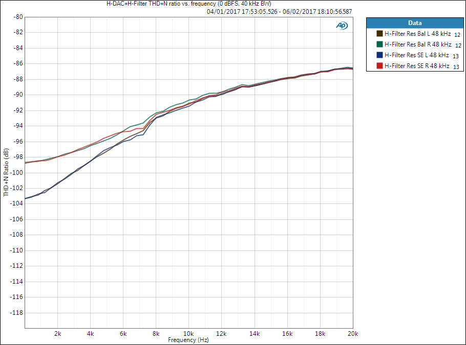
 and then with fixed resistors. Here the difference with resistors is not as big as in other measurements.
 Below fixed-resistor results are compared with H-DAC and Addon H-PreAmp (thin lines).

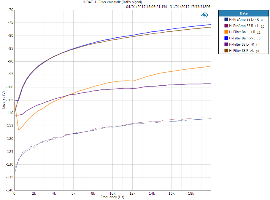
Crosstalk
This is where cheap potentiometer really shows it should not be used. Results are below, compared to Addon H-PreAmp (thin lines). First of all, difference between channels is enormous 15 dB or more. Secondly, even the better channels is 15 dB weaker than H-PreAmp.
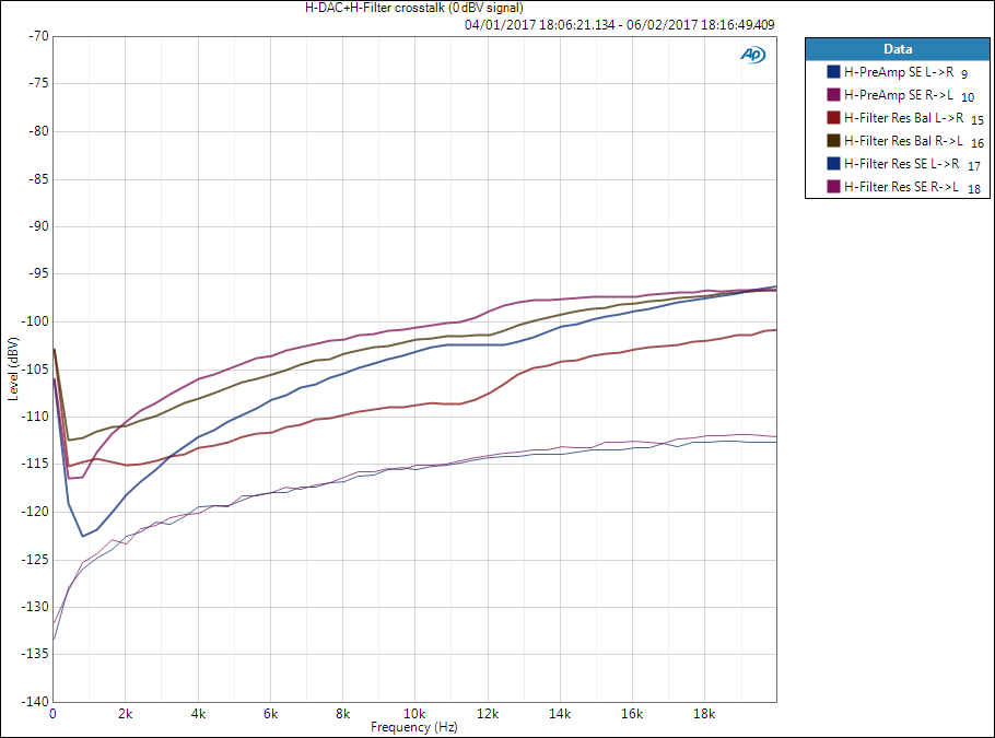
 Below are results with fixed resistors. Addon H-PreAmp is still clear winner but fixed-resistor implementation wins cheap potentiometer by miles.
Conclusion
It has been clearly seen that it is worth investing in a quality potentiometer. The results are likely more consistent between channels and show improvement in crosstalk. Two cheap potentiometers which were tested both also showed significant tracking error – even few dB between channels. The challenge here is to find good potentiometer – I checked some Alps and Bourns models and even £10+ potentiometers may have as large as 3 dB tracking error specification. Good potentiometer will not be cheap but it also does not guarantee that expensive potentiometer is going to be good. Digital volume control or stepped attenuator IC can easily beat potentiometer in crosstalk and channel balance even if they may lose slightly in noise performance.
Addon H-Filter can achieve very good performance if the pot is well chosen. With fixed resistors the audio performance is better than Addon H-PreAmp (except crosstalk) – and may I remind that we have very cheap NE5532 opamps here. Also other components are pretty much standard stuff.
I will try to repeat the measurements with good potentiometer (if I can find one..) at a later time. With better layout (getting some area by giving up the rectangular hole for H-DAC electrolytics) even the crosstalk figure could be close to other designs.
Using the pot is not very convenient as the gain curve is a bit odd and there is no maximum gain due to reasons explained in the beginning. I am not currently using this board myself but this was more of an experiment.
Files
- v1.0A PDF files
- Schematics
- Component placement top
- Component placement bottom
- BOM example (without exact potentiometer model)
- Check carefully before making component order
- Prices are in GBP, without VAT, and not up-to-date)
References and additional information
- NE5532 (TI) datasheet
- Bruno Putzeys: The G Word, or How to Get Your Audio off the Ground
- Source for the idea of the potentiometer circuit, introduces balanced preamplifier circuit along with what balanced connection means regarding ground
- Elliott Sound Products: Design of High-Performance Balanced Audio Interfaces (by Bill Whitlock)
- Good reading what balanced interconnection actually means and what it does not
- Rane: Pin 1 Revisited
- Introduction to The Pin 1 Problem (in XLR connectors)
Version history
Schematics and PCB
- v1.0A Initial version
This page
- 6.2.2017 Initial version