
- Dual Trafo Board and SmartPSU3 modules
- Two 3-channel power outputs for DAC-preamplifiers, total current capability being approximately:
- +14 V, 250 mA
- -14 V, 250 mA
- +7 V, 500 mA
- Over-current, under-voltage, and over-temperature protection provided by SmartPSU3
- Error codes blinked by the front LED
This is the device where Dual Trafo Board and SmartPSU3 were originally designed for – external power supply that is simple yet provides some protection in case something goes wrong in the target device. Its current output capabilities are somewhat limited but enough for small DAC and preamplifier. It was designed for HP Pre 2016 although headphone output power may be somewhat restricted with this power supply.
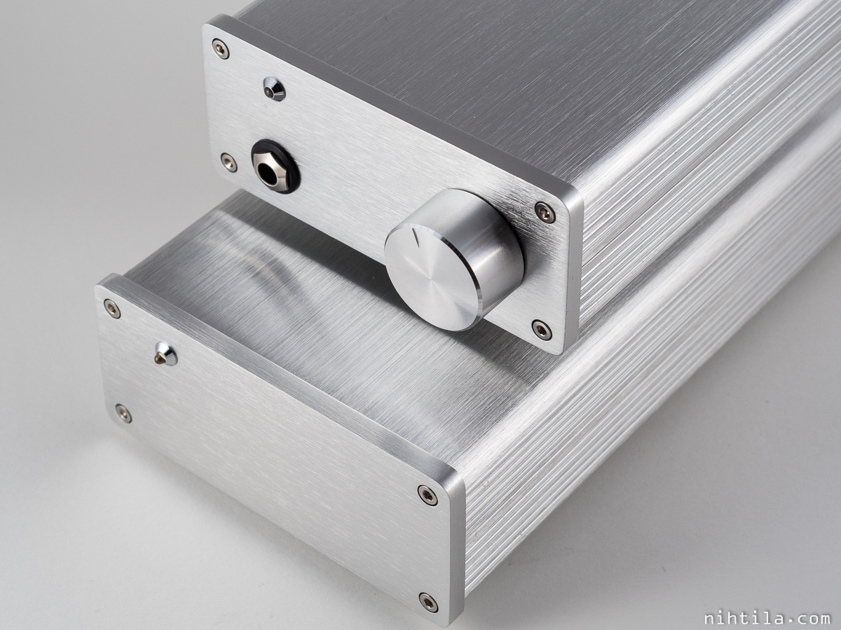
HP Pre 2016 and PSU Pre 2016
Design
This page does not explain detailed functionality and design of Dual Trafo Board and SmartPSU3 , see their corresponding pages for more information.
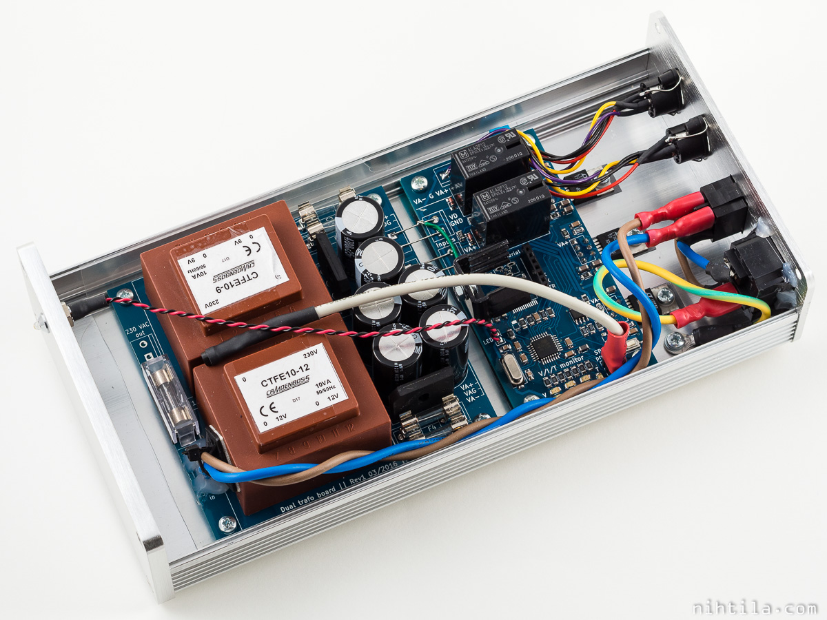
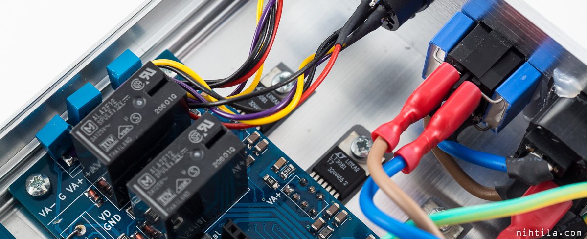
The aluminium enclosure is from eBay and is rather snug fit for the two boards. Furthermore, there are no vents for air circulation. Due to that, I have added one external temperature sensor to SmartPSU3 to monitor the temperature inside the enclosure. It is an old DS1820 temperature sensor seen on top of the transformers in the photo below.
Mains wiring is connected to the Dual Trafo Board with solder and hot glue, and cable tied to the transformer so it should not get loose under any circumstances. Note that the mains socket on the back panel is not mainly secured by hot glue, the glue is there just to keep to connector still as the hole is slightly too wide. Safety earth lead is tightened on the bottom of the enclosure. Note also the plastic sheet under the transformer board.
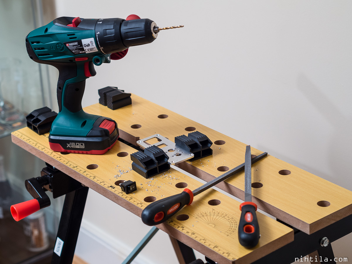
I did not order custom made backpanel for this device as the panel is very simple. Instead, I made the holes in my flat with the tools I have. Which is mostly tools from Lidl 🙂 Mains socket hole was pre-made as the enclosure came with the socket.
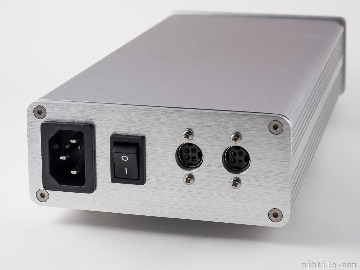
I have used 4-pole mini-DIN DC jacks and plugs from Mouser/Maplin. They are not mechanically superb but decent anyway. The locking mechanism just does not work as the backpanel is so thick, or holes too small. I was looking for proper multi-conductor cable with thick enough conductors but could not find any. Eventually I used FTP Ethernet cable and tied the pairs together for 4-conductor cable. Most Ethernet cables are unshielded UTP type but in FTP cable the pairs are inside foil shield which can be connected to the connector shield.

Measurements and tweaks
This section deals with
- Mains switch noise measurements and suppression
- Relay contact noise measurements and suppression
Mains switch noise
I noticed large spikes with rather high rise time when switching the power supply on or off. Unfortunately I do not have captures of audio output anymore but they were present also at the audio output. As I located the source to be the mains power switch, it means the spikes go through the whole system – transformers, regulators, and the whole H-DAC board. I do not understand completely how but possibly because of very high frequency content. I do not know the exact root cause either but must be some kind of contact bouncing and sparking. Anyway, here are some results regarding the issue.
These spikes are unlikely to break anything as their energy content is so low. I presume they could still cause some issues, certainly I do not want to see them. The amount of noise also depends on the switch – not all mains switches are probably as bad as mine.
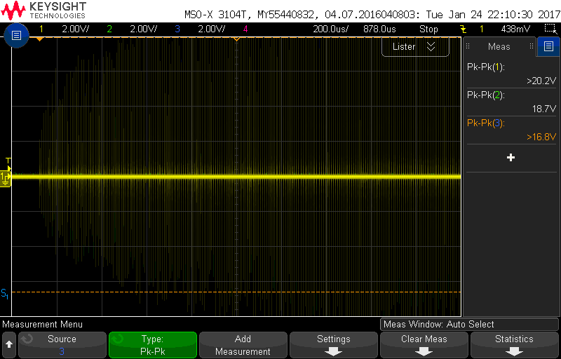
Below are the mains switch noise seen after Dual Trafo Board, meaning after transformer, rectifier, and filtering.
Mains switch on:
Mains switch off – this high amount of noise was not always visible but occasionally:
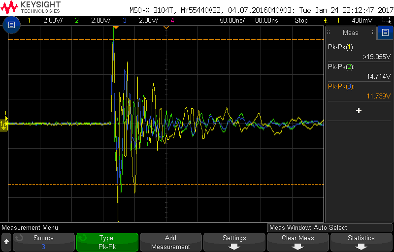
Below are switch-on spikes zoomed in to show their time-scale is in the order of nanoseconds:

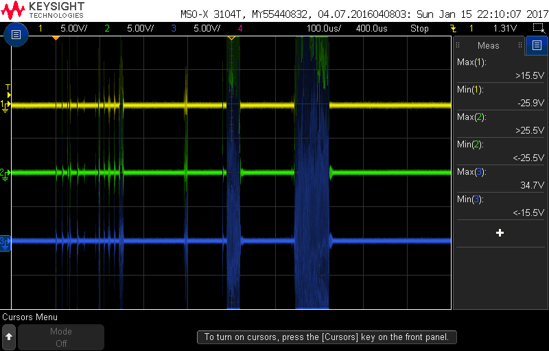
Below are captures after SmartPSU3 when mains switch is switched on and off. It is clear that these noise comes through everything. Similar spikes could be seen all the way at the audio output (unfortunately I do not have captures of those).
SmartPSU3 output, mains switch on:
SmartPSU3 output, mains switch off:
Solution
I placed 10 nF X-capacitors across mains switch contacts to see if they suppress the switching noise. I used these values only because they were the only ones I found, and two caps were used as I have 2-pole switch. X-rated capacitors are designed for mains voltages, in fact to be used between live and neutral. The results are excellent. Occasionally there were more spikes than on the images shown but improvement is remarkable. Not only the amount of spikes is only fraction of what it used to be, their voltage value is also significantly lower.
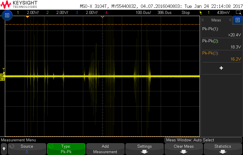
Mains switch on, X-caps installed:
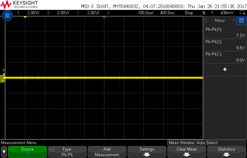
Mains switch off, X-caps installed:

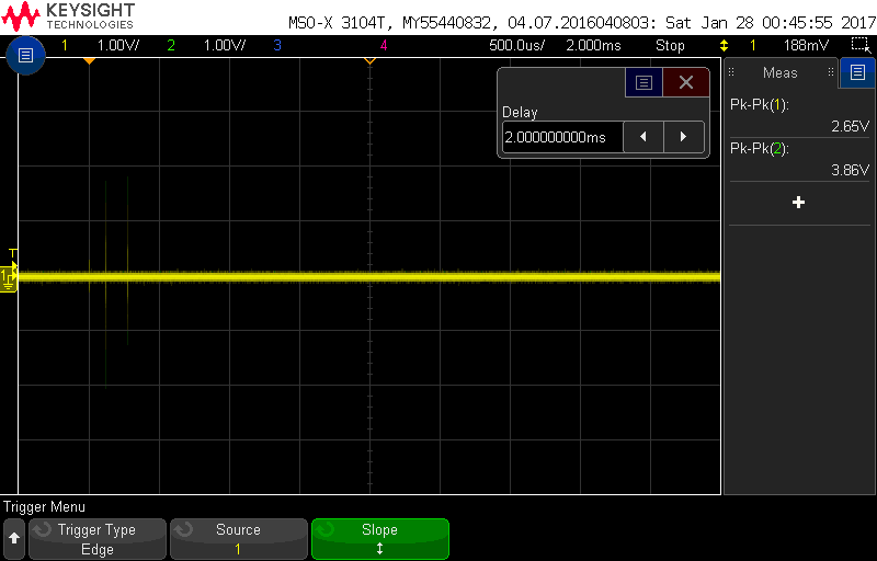
Similar to above but zoomed in:

Even after installing the X-caps I can see the switch noise at the audio output of H-DAC. The amount is significantly lower, sometimes difficult to even see, and they are lower but still present.
H-DAC audio output when HP PSU is switched on:
Relay switching noise
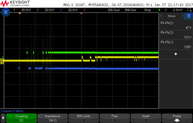
Another contact switching issue was with SmartPSU3 output relays, causing very nasty looking series of spikes. Like mains switch noise, this also depends on the used relay. However, all relays cause some contact bouncing.
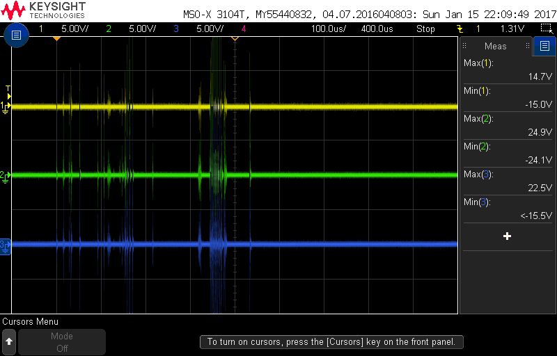
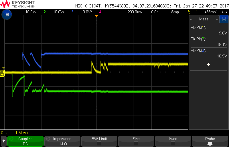
SmartPSU3 output relays on – look at the vertical scale of this and the voltage values! Peak-to-peak values go over 100 volts.
I tackled this issue by placing 1 uF capacitors at the SmartPSU3 outputs after relays – I do not have anything at the outputs on the schematics. 1 uF value was chosen only because these were physically the size I could solder without removing the PCBs from the chassis. We still have the contact bouncing there which is a mechanical phenomenon but this time it does not cause large amount of huge spikes:
Below is a photo showing the capacitors installed afterwards. On the right-hand side are the two X-caps next to the mains switch and on the left-hand side the three 1 uF output capacitors.
Version history
The device
- No changes since initial version
This page
- 5.2.2017 Initial version