
Measurements and experiments carried out on a more spacious AK4490 test board
- Better understanding on improving AK4490 performance
- Encouraging results regarding Wee DAC performance goals
- Massive boost of 10-15 dB in THD+N at low frequencies
- THD+N at 1 kHz measured beyond -110 dB on test board
- Does not mean Wee DAC will achieve these though
- Modifications will increase BOM cost so need to consider the benefits and find a good compromise
Earlier measurements recap
Four weeks ago I wrote the first Wee DAC measurement update and here is a recap of it.
Initially I had issues because of powering the supplies directly from bench PSUs. This kind of indicated that something in the power stuff is quite sensitive here (at least indicates when thinking about it now afterwards..). By using W-PSU with on-board regulators, THD+N at 1 kHz went up to -99 dB. VREF references emerged to be the sensitive bits. When adding loads of capacitance on VREF lines, things improved significantly and the best THD+N measured was -108 dB. That is an excellent result; however, it was with two massive 2200 µF capacitors, see a photo of one below. Not very viable in this form factor, and not so elegant either.
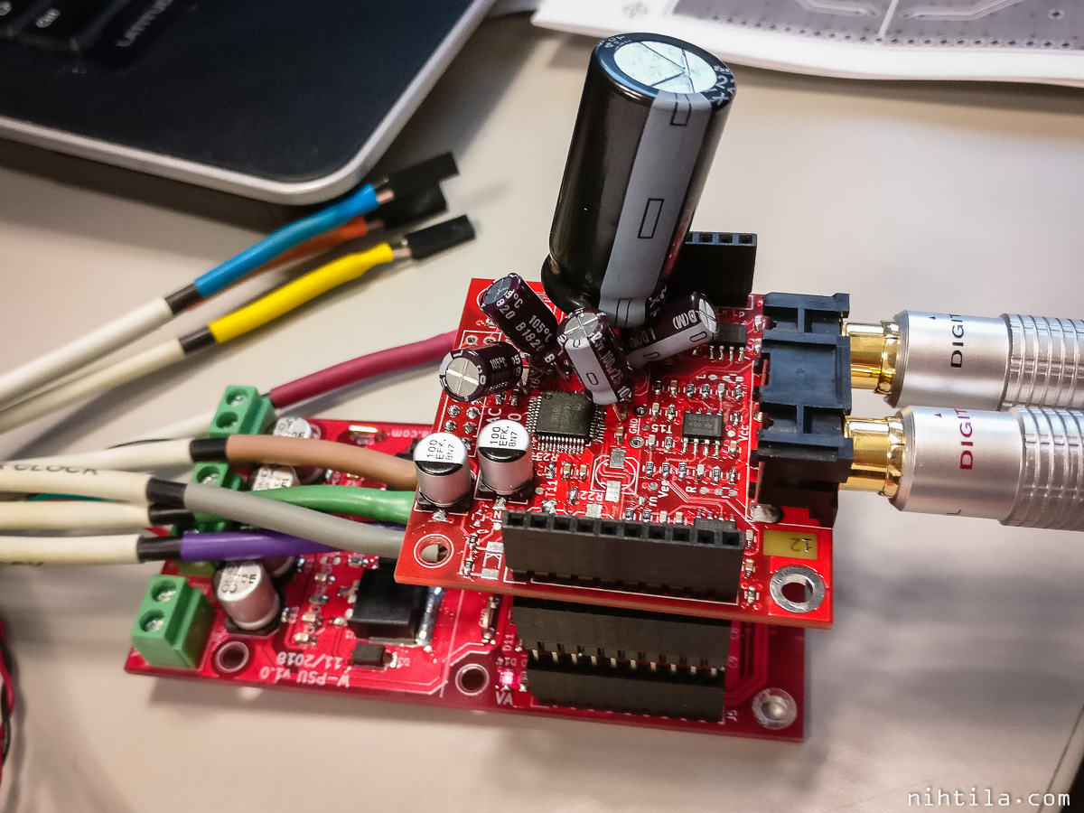
W-DAC with 2200 uF capacitor – and to get the best results two were required.
And that figure was THD+N at 1 kHz. At lower frequencies things still were not great. I would assume THD+N vs. frequency graph to be nearly flat but it was far from that. More tests indicated that it was still an issue supplying VREFs.
THD+N at lower frequencies was significantly increased.
Before moving forward, I also ordered a couple of different high quality polymer and tantalum capacitors to see if they would flatten the THD+N vs frequency graph, but they did not bring notable improvements over bulk capacitors.
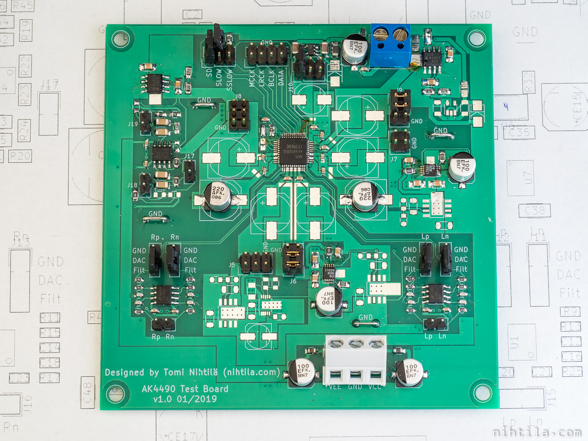
AK4490 test board
Before re-spinning the W-DAC PCB, I wanted to make a more spacious test board that gives the opportunity to experiment a bit and see what is important around AK4490. The board has numerous supply options for VREFs, VDDs, and other supplies, using either LT3042 or ADP7118 regulator or opamp buffer for references.
Findings and performance improvements
I did quite a lot of tests; however, there are so many variables that not everything can be tried in reasonable amount of time. Here are some of the findings of these measurements.
These results focus on VREFs as these seem to be the main concern on AK4490. Quick tests showed that VDDL and VDDR are not that important although these should be of decent quality as well. AVDD does not really matter much and can be taken from DVDD supply.
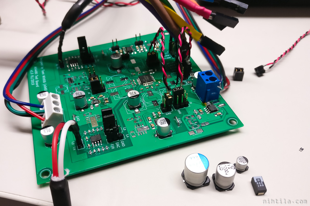
AK4490 test board on measurement bench.
Voltage regulators and buffers
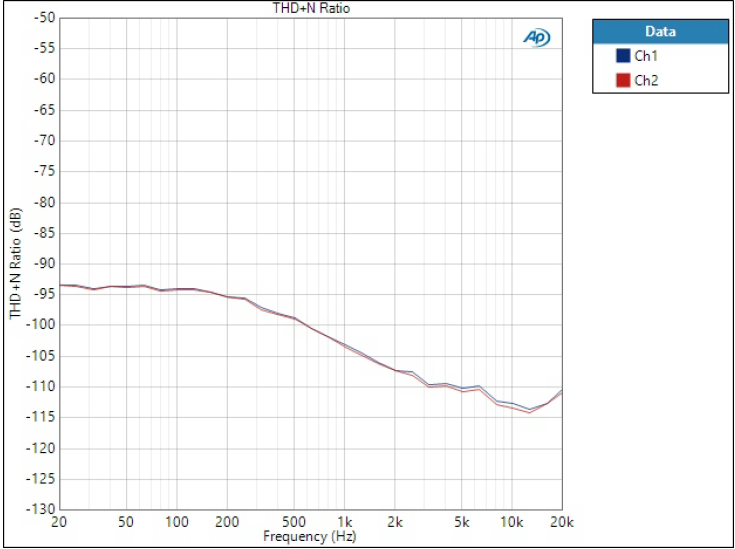
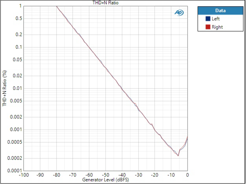
First of all, Analog (ex Linear) LT3042 is a superb regulator and gives excellent results when used for supplying VREFs. Another benefit is that there is no need to use a massive electrolytic capacitor which is especially good on a small PCB. With LT3042 and solid layout THD+N at 1 kHz and near full-scale reached -111 dB. Moreover, THD+N vs frequency is almost flat now, giving huge improvement of 10-15 dB in lower frequencies compared to initial W-DAC results. This is what I hoped to see!

THD+N ratio vs amplitude using LT3042
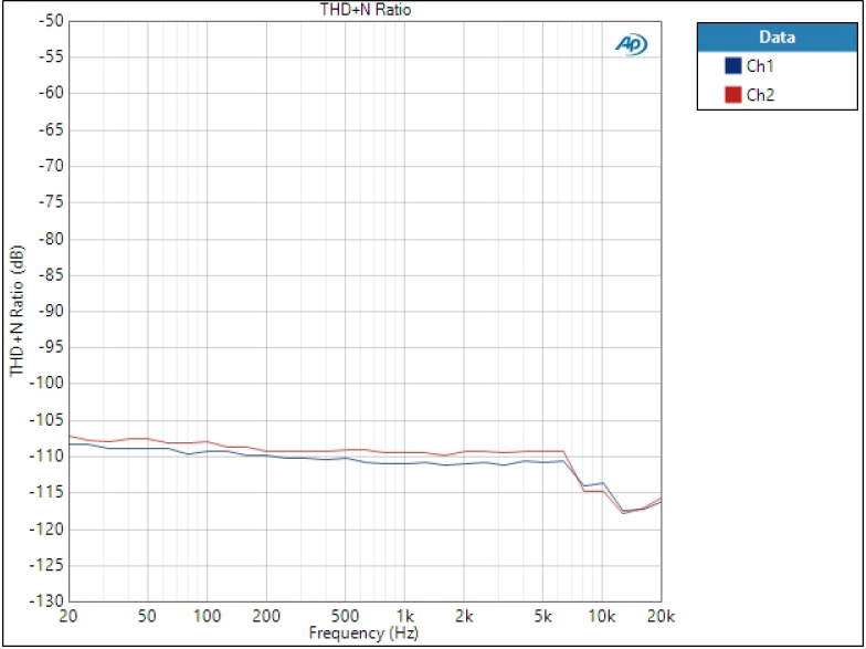
THD+N vs frequency at 0 dBFS, using LT3042.
There is slight difference between left and right channels near full-scale level as right channel is wired from LT3042, while left channel has solid copper connections. These references are very sensitive and even a short and solid wire deteriorates the performance slightly, indicating layout may be critical as well.
I also tried ADP7118 as it is a lot cheaper than LT3042. However, the results were not that good although still better than the initial W-DAC results. I also tried LM4562 opamp buffer for references, as for example on AK4490 evaluation board an opamp-based buffer (with discrete components) has been used. Again, results were good but not as good as LT3042. I believe one can make an excellent opamp buffer with careful design using also discrete components. However, the overall cost would come close to LT3042 anyway and the solution would be a lot larger than the tiny LT3042.
Increasing reference voltage
While nominal voltage for analog supplies and references is 5 V, the maximum rating is 7.2 V. Therefore, you can find lots of discussions on forums people running these supplies with higher voltages and reporting better results. And it does bring some benefits but it is not that simple. I did my measurements with 6.65 V because it still allowed me to carefully use 6.3 V capacitors (and because using 100k and 200k resistors in parallel for setting LT3042 voltage just happened to give 6.65 V).
First of all, output level is directly proportional to VREFs. As noise level seems to remain constant, increasing signal level by increasing VREF boosts dynamic range. By moving from 5 V to 7 V one can expect around 3 dB boost in dynamic range – which is always beneficial.
THD+N is a bit tricker. Higher VREF re-shapes the curve quite a bit. This leads to lower distortion at lower signal level but higher distortion near full scale. For example, at -20 dBFS THD+N was 3 dB lower when using 6.65 V VREF. However, the increase near full scale is very steep, leading to 7 dB worse distortion at 0 dBFS. Compare the graph below to the one above. Which one to prefer is more like a design choice. I think I will keep the voltages at 5 V.
THD+N ratio vs amplitude, VREF at 6.65 V.
Towards new version of W-DAC board
These are only results of the test board. I will still carry out a couple of tests and then need to decide what changes do I implement on a new version of W-DAC board. It will still be a small board with restrictions in terms of real estate, other components, and also price.
I will use LT3042 as it is both very small, especially given it does not need huge electrolytics, and very good. The only downside is price – it costs more than the AK4490 DAC chip. Therefore, I do not want to use a separate IC for all four supplies as it would blow up BOM cost. A compromise is required here and I do not know yet whether I try to get along with only one regulator or should I use two. Anyway, there will be cost implications but with these performance improvements it is worth it.
References on AK4490 seem to be quite sensitive so the final W-DAC performance remains unknown until a new board is designed, built, and measured. I hope to get as close as possible to these test board results but there will likely be some deterioration, depending on how I will end up connecting the supplies, how many regulators to use, and layout of course. And always a pinch of black magic.
7 comments
Glad you sorted out the problems! Although I wonder if you can measure the performance from the power supplies directly. instead of the resulting sound! Did you changed anything else besides the power supplies and the caps?
I never thought on supplying each channel with different PSU’s and seeing the difference. Clever idea!
PS: Will the input only be SPDIF/coax or do you plan adding USB support later?
Probably with right measurements you could measure the supplies directly and get differences there but it could still be difficult to see the impact on output without measuring the output. It would be interesting to know the underlying mechanism what affects the performance but could be tricky to measure. After all the noise and distortion here are so small.
I focused on supplies here, and mostly on VREFs as they tend to be the sensitive ones. Of course the layout is difference now as well, and will be again on a new W-DAC PCB.
I think often separate supplies for each channel are used crosstalk in mind. Here the layout could matter the most. I see performance deterioration even when using short wires to power VREFR from VREFL supply. That makes me wonder that would I see that deterioration on PCB as well if one VREF is farther away from the regulator. If I use two, I could have one on each side of the board and have nice symmetric layout. But will see what to do.
At the moment the idea is only to have Toslink and Coax as I don’t have my own USB solution and they are not very easy to make. One could use W-DAC with external USB-I2S module without W-Input. Although then you would lose Toslink and Coax. Need to think about that still. Switching between Toslink, Coax, and I2S is a bit cumbersome.
Putting a second regulator on the bottom side could help with the simetry, but I’ve been told that the vias have a nasty inductive behavior. That might pull the bandwidth a bit down, no?
Hi! I still have not understood where the problem is now. You wrote that you take the LT voltage regulator and the situation has improved. But why? Is the voltage more constant? Do you have less noise? Does it have better power delivery capability?
I don’t know the underlying mechanism what causes the improvement. And to be honest probably will not know.
LT3042 is one of the best regulators out there with extremely low noise, very high PSRR, high bandwidth, and so on… The actual noise floor of the audio output has been pretty much identical with all things I’ve tried so at least there the noise is not visible – unless it has a different mechanism deteriorating the performance. Distortion is the problem here but I do not know what causes it. You wouldn’t expect PSRR being the issue either as I’m feeding these regulators with a bench PSU. Bandwidth.. I don’t know, in the first measurements it was the distortion at hundreds of Hz that was problematic.
VREFs should not really draw current. But for some reason besides being clean it is also beneficial to have very low impedance power connection (possibly over a wide bandwidth) by a very good regulator. These are of course common requirements for good power supply but why it matters so much here – don’t know. Maybe only an AKM designer can answer that.
It’s also good to recall that we are talking about levels near -110 dBV here, thus extremely small things may matter.
The LT is very expensive and e.g. a LM317 would be better. I really suspect that it’s just a grounding problem.
The LT is expensive for a reason. Compare the datasheets of LT3042 and LM317.
I don’t think it is a grounding problem, especially on this test board where the layout is quite solid and there is nothing else than AK4490 and its external components. And comparing two different regulators give different results.
It would be interesting to try LM317 though which is still an excellent choice for many applications. And I am not saying LT3042 basically being the most expensive one is the only way to achieve this top performance. Very likely there are cheaper options that would provide the same result. In that sense it would be useful to know what is causing the distortion so one could pick other options based on datasheet. However, as there are dozens of good regulator options, trying a lot of them is very time-consuming. Especially as here doing some dodgy wired prototypes will likely not show the real performance, so one would need to make test PCBs. Moreover, LT3042 is a good option for this form factor as the overall solution is very small.
Comments are closed.