
- Placeholders for two small, approximately 10 VA, dual-secondary PCB transformers
- One transformer in series configuration for dual (analog) supply
- One transformer in parallel configuration for single (digital) supply
- Independent circuits, no common ground
- Supports the most common transformer pinouts
- Fuses, rectifier bridges, and filtering capacitors
Dual Trafo provides three unregulated low power voltage rails for mixed signal devices, such as DACs. The board can be followed by a regulator board such as SmartPSU3 or SimplePSU3 (without filter capacitors) or it can be used to feed application board’s regulators.
This 10 by 10 cm PCB can accommodate two approximately 10 VA dual winding transformers, one in series and the other in parallel secondary configuration. Therefore, it can provide at least 200 mA in +15/-15 V range for analog components and few times that in 5 V range for digital supplies.
Disclaimer: This design uses possibly lethal mains voltage. Do not try to build this or similar device without extensive understanding of electronics and electrical safety. Also check the regulations in your country. If you do build your own mains-powered device, always use properly connected safety earth lead, both primary and secondary fuses, safe clearance and extra insulators around and under the components and PCBs. Also make sure none of the mains leads or components can touch any metal parts if they get loose. Always disconnect your device from mains power completely when not in use.
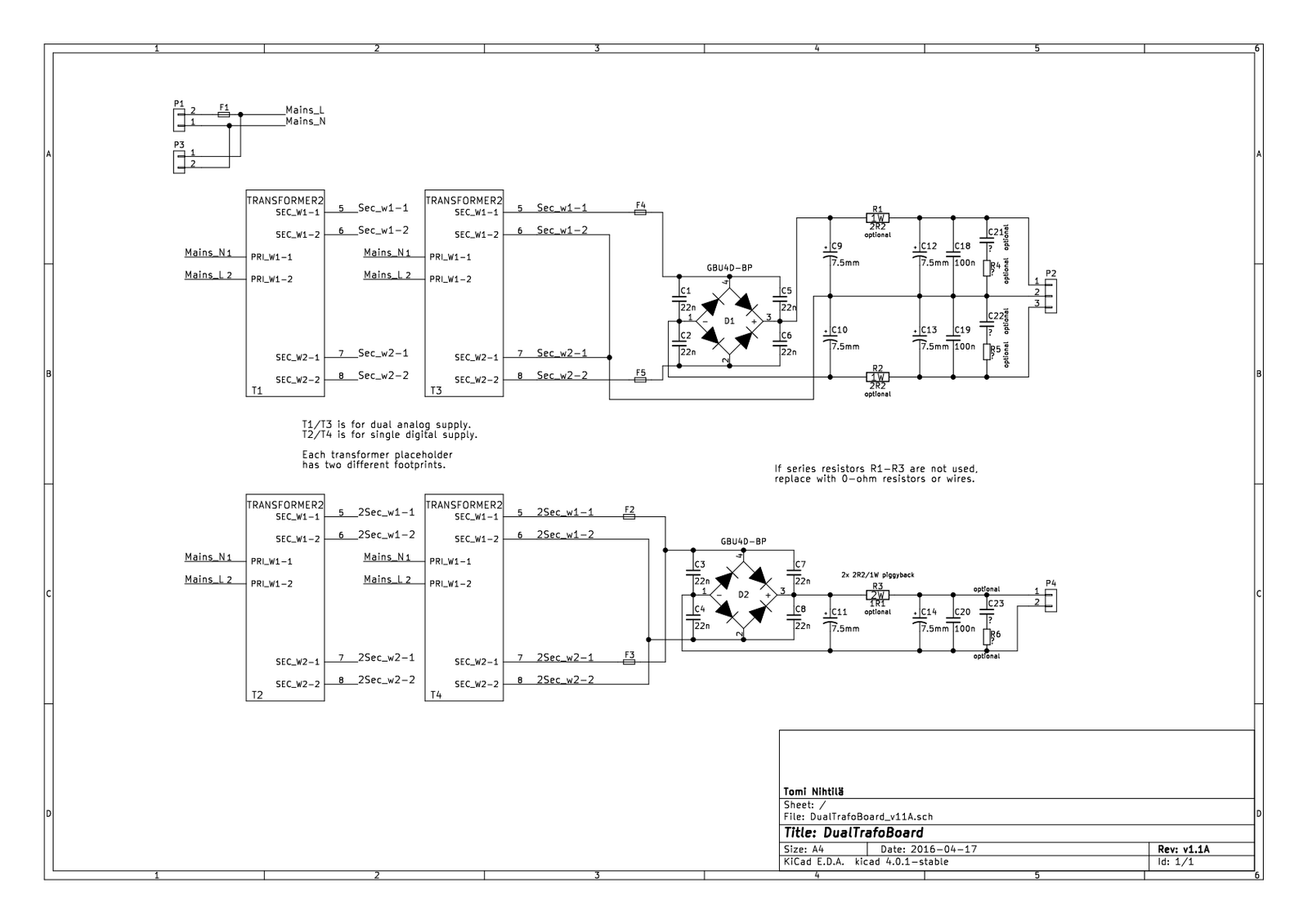
Design and schematics
Schematics are very simple as this is just two separate unregulated power supplies. Transformers are followed by secondary fuses in each winding and rectifier bridges with bypass capacitors to reduce switching noise. There are placeholders for two 7.5 mm pitch electrolytic capacitors per rail with series resistor in between. These resistors can be shorted if not used. Snubber circuits R4-C21 etc. are optional. Make sure chosen capacitors have adequate voltage ratings. Digital supply often has higher power requirements but also lower voltage so higher capacitance and lower voltage capacitors can be used.
Mains fuse F1 should always be used. P3 is for daisy-chaining 230 V boards and is taken after the fuse. There are also fuses for all secondary windings that should be used; it is always safer to protect all windings as sometimes overloading or shorting secondary may not blow the mains fuse.
The two circuits are separated and do not have common ground.
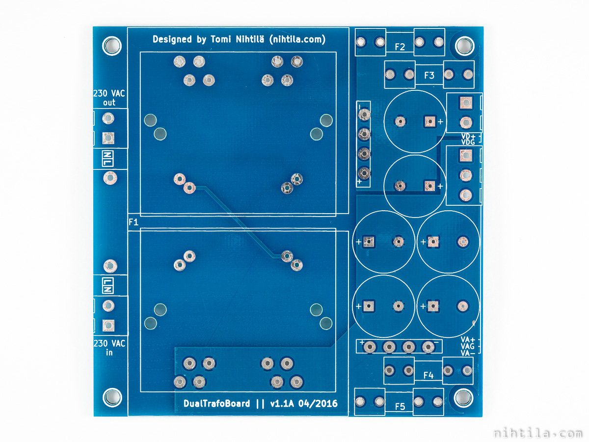
Layout
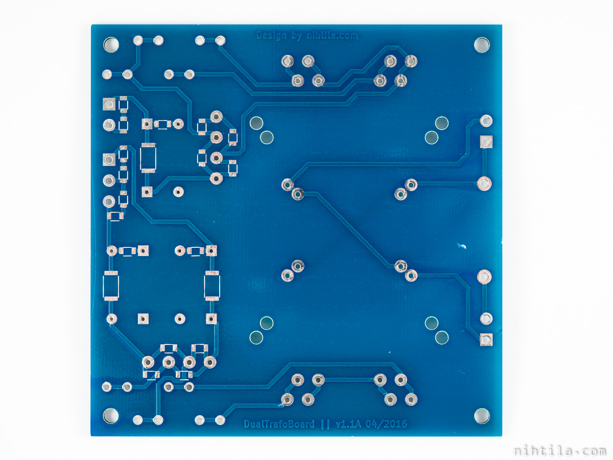
PCB is a simple 2-layer 10×10 cm board. I have tried to keep as long distances as possible between primary and secondary circuits.
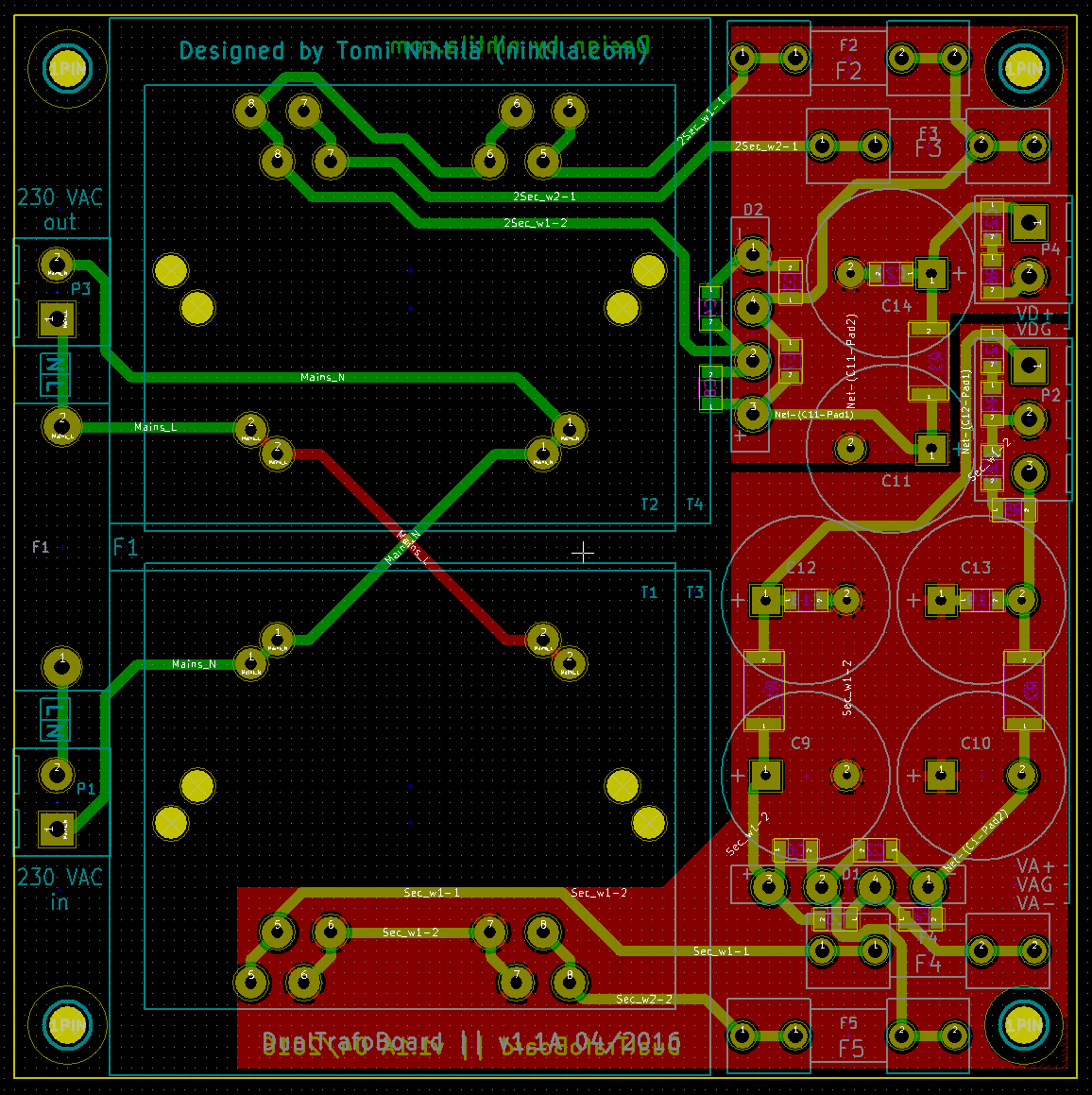
Note that in the PCB used in the main photo the secondary fuses are too close to each other; that is the version 1.0A. Below is the version 1.1A where these are interleaved so that the metal parts of the fuse holders do not touch each other. Still ensure your chosen fuse holder model have enough clearance.
Layout image
Safety
It is your responsibility if you decide to build a mains-powered appliance and connect it to your mains outlet. Here are some thoughts to consider, but not limited to these, when dealing with possibly lethal voltages:
- Check your country’s regulations regarding electric safety; it may even be forbidden to build such devices
- Always use safety earth lead properly connected to your metal enclosure and ensure your wall outlet has safety earth connected
- Buy your transformers and mains rated components from trusted sources
- Use fuses both on primary and secondary sides of transformers
- Use safe air gap and extra insulator, e.g. a sheet of plastic, between the bottom of your PCB and metal enclosure; also make sure this sheet cannot slip away
- First make sure your mains leads cannot get loose, then make sure they do not touch anything if they get loose anyway
- Also ensure there is no other conducting material inside your enclosure that can get loose and cause shorts
- Always disconnect your device from mains when not in use
- Remember that besides yourself, your gadget may cause injury or death to someone else
Files
v1.1A files in PDF:
- Schematics
- Component placement top
- Component placement bottom
- BOM (check that everything is correct)
Version history
Schematics and PCB
- v1.0A Initial version
- v1.1A
- Secondary fuse holders (F2/F3 and F4/F5) moved so that their metal parts are interleaved and do not touch each other easily
- Possible changes for next version
- Add reference designators on silk screen?
This page
- 1.1.2017 Initial version