
- Three linearly regulated fixed outputs
- One dual supply intended as analog supply
- One single supply intended as digital supply
- Common ground
- Undervoltage, overcurrent, and overtemperature monitor and protection
- Maximum 1 A per channel, depending on the design and cooling
- Output relays
- Software-controlled monitors (Arduino compatible)
- Can also be used without microcontroller
- 2x LT3081, LT3091, ATmega328P
SmartPSU3 provides three fixed relay-switched regulated and monitored low-power voltage outputs. As it has one positive and one dual positive/negative supply, it fits well for mixed signal audio applications, such as DACs, where dual analog supply and single digital supply are required. All channels use linear regulators for low-noise output.
The regulators have hardware current limits and on-board microcontroller adds undervoltage and temperature limits. Therefore, hardware-based current limits react fast while software isolates the load with relays in case of overcurrent, undervoltage, or overtemperature. Microcontroller circuit is Arduino compatible.
Microcontroller only monitors the outputs and controls output relays; output voltages and currents are fixed by resistor values and cannot be changed by the microcontroller. In fact, the board can be used without microcontroller as well.
Design and schematics
SmartPSU3 is built around Linear regulators LT3081 (positive, 1 A) and LT3091 (negative, 1 A). Besides low noise these rather expensive regulators offer a range of integrated monitoring functions. LT3081 has hardware current limit, current monitor output, and temperature monitor output. LT3091 has hardware current limit and current monitor output. Output voltage and current limits are set with resistors. These regulators are in 7-pin TO-220 package which can be installed onto a heatsink or device chassis.
All monitor signals are connected to analog inputs of ATmega328P microcontroller. It is then the task of the software to disconnect output relays in case of undervoltage or overcurrent in any of the channels. In addition, temperature monitoring is available in LT3081s. 7 LEDs are provided to indicate these error conditions.
ATmega328P can be programmed with compatible SPI programmer. However, when pre-programmed bootloader and on-board FT232RL (or external USB-serial adapter) are used, the device can be made Arduino compatible and programmed with the Arduino IDE and USB-cable.
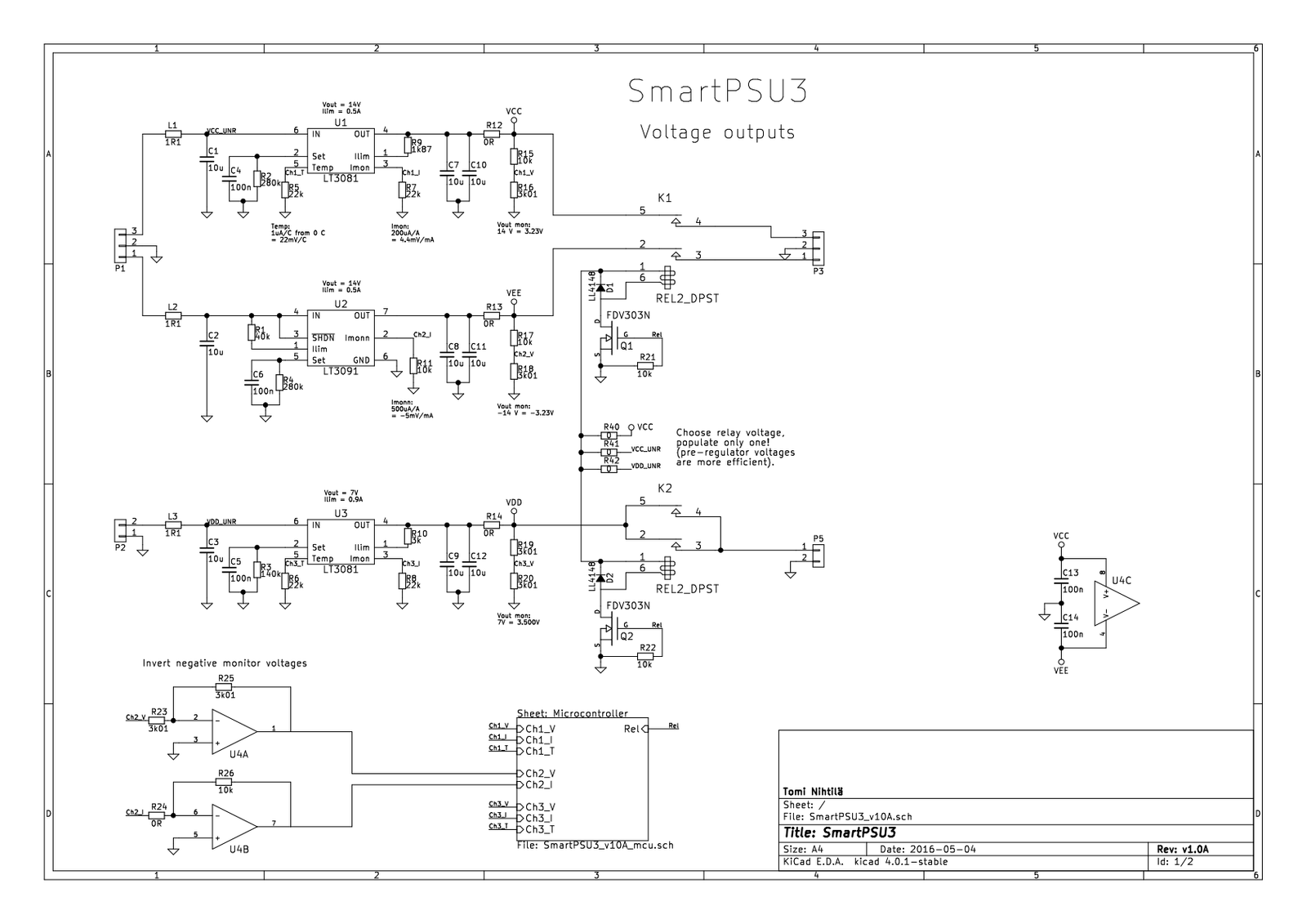
Regulated outputs
Only one channel is explained in detail, other channels have corresponding components and are set up in similar manner. See LT3081/LT3091 datasheets for more information. These regulators function in very similar way – only some formulas for external components varies slightly and LT3091 lacks the temperature monitor output.
L1 and C1 form input low-pass filter. L1 can be inductor or resistor; inductor creates steeper filter but may generate resonances. L1 can also be shorted. Note that C1 has small capacitance so properly filtered DC input (big electrolytic capacitors after rectifier or switched mode power supply, if you wish) is required.
R2 sets output voltage – 20 kohms equals 1 volt so 280 kohm is 14 V. C4 stabilises this set pin (as well as a guard ring on PCB). R9 sets hardware current limit. Pin 5 is temperature monitor output, sourcing 1 uA per degree celsius. Similarly, pin 3 is current monitor output, sourcing 200 uA per one ampere of output current. Choose resistors R5 and R7 so that the voltage is always less than 5 V (microcontroller AD-converter reference). C7 and C10 are regulator output capacitors (populating one should be enough). R12 can be used as a series resistor, for example if output leads from SmartPSU3 board are long, just note the decreased load regulation in that case. R15 and R16 provide voltage monitor for the microcontroller. Refer to LT3081/LT3091 for more details, and for choosing the resistors.
With LT3091 current and voltage monitor outputs are negative and therefore inverted with U4 (use any opamp you wish, I had only NE5532 at hand when building the prototype) as microcontroller cannot handle negative voltages. It is also due to these monitor connections to the microcontroller that the outputs are not floating but share common ground.
Outputs are connected through relays which are off by default. Relay coil voltage is selected with R40, R41, or R42. Populate only one of these! Choose the voltage closest to your relay coil voltage. Voltages before regulators (VCC_UNR or VDD_UNR) are preferred.
If you do not use microcontroller, do not populate relays but just short the relay contact pads.
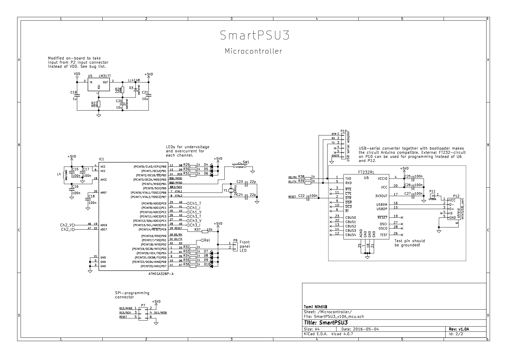
Microcontroller circuit
ATmega328P microcontroller is used to measure the voltage, current, and temperature monitor signals and to control indicator LEDs and output relays. It cannot adjust output voltages or current limits; therefore, microcontroller circuit is optional.
Separate 5 V supply around U5 is used for microcontroller and peripherals to be independent from the VDD. C20 is optional, improving regulation. If C20 is populated, also populate D3. There is a bug in v1.0A where VDD instead of VDD_UNR sources U5. Now microcontroller resets if VDD dips which happens at startup if there is large capacitance at load circuit, as LT3081 hardware current limit kicks in due to inrush current. Also, U5 does not even regulate unless VDD is higher than 5 V + dropout voltage. Luckily there is a simple mod for that, shown below: cut one trace and solder one wire.

LEDs D4-D10 are connected to I/O pins to indicate overload and undervoltage in all three channels, plus one LED dedicated for overtemperature. All 8 AD-converter channels are used for reading voltage, current, and temperature monitor signals. SW1 can be used in software.
FT232RL (U6) circuit provides support for Arduino IDE. Arduino-compatible bootloader can be programmed via P7 and after that the device can be programmed with Arduino IDE. The circuit corresponds Arduino Nano. See separate page regarding Arduino compatibility.
Edit 29.8.2018. FT232RL test pin should be grounded! Few boards I have built so far have been working fine with the pin floating but now I got one that did not. Datasheet says it should be connected to ground. Luckily there is a ground pin next to it so they can be shorted.
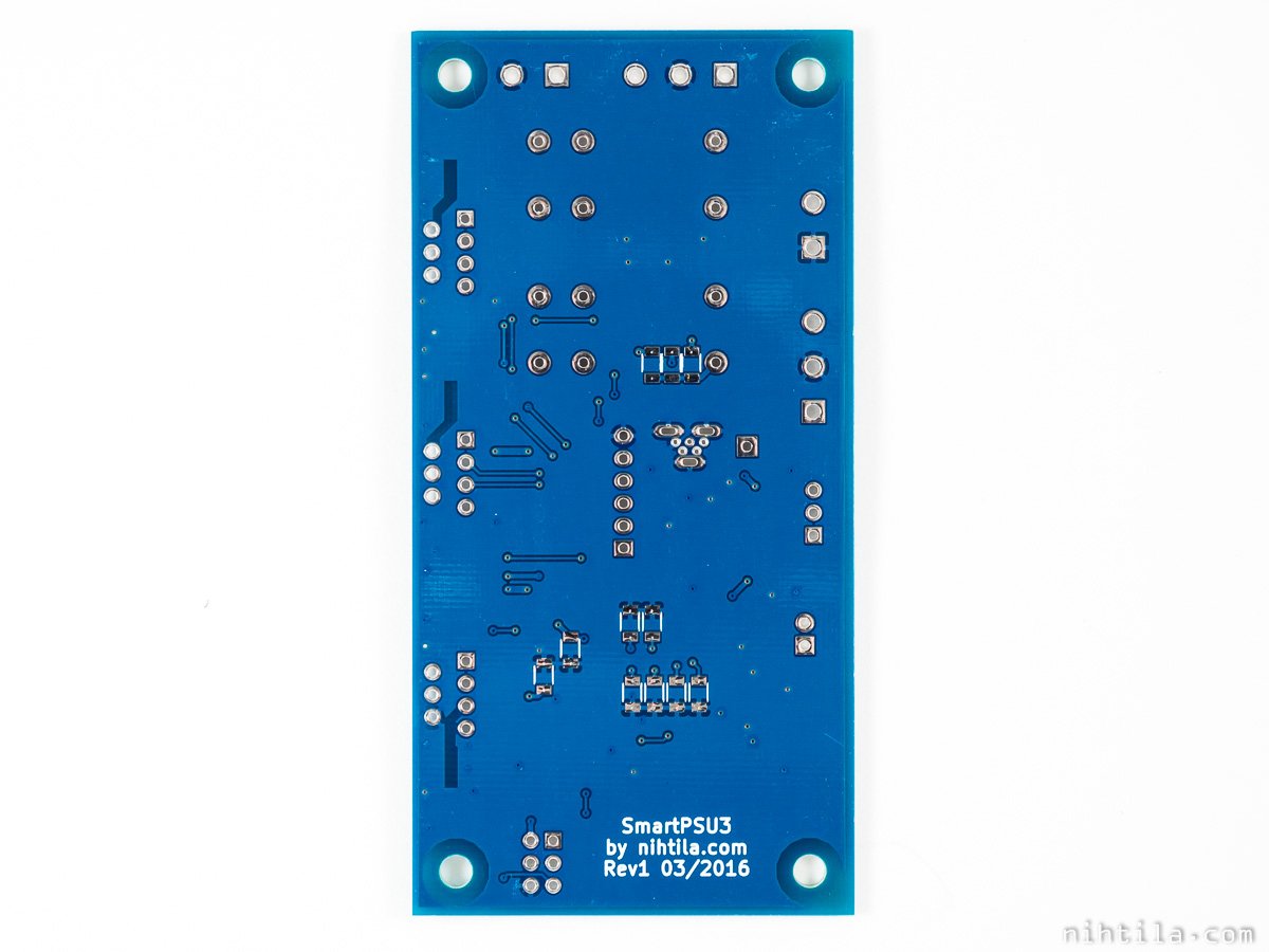
Layout and components
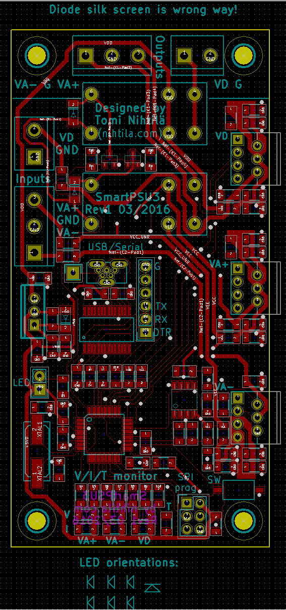
2-layer PCB is 5 by 10 cm and mostly SMD components are used due to performance and space reasons. All passive SMD components are 1206 packaged so they are easy to solder. ATmega328 and especially FT232RL are slightly smaller pitch IC packages.
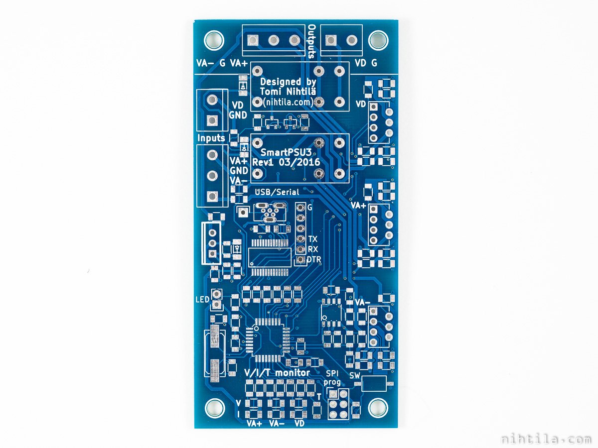
Layout image
Software
The software used in the prototype HP Pre 2016 can be found here and easily modified for one’s needs.
Basic functionality is to constantly monitor all ADC channels and disconnect outputs when violation of limits occurs. All limits are defined in the beginning of the code using clear numbers. Also schematics resistor values are defined there so it is easy to keep the functionality the same even if changing resistor values. Current stage of output voltages, currents, and temperatures can be read via USB serial port by pressing SW1.
If one of the limits is exceeded, output relay is switched off and fault condition showed by LEDs: on-board LEDs show directly what triggered the fault but front-panel LED blinks an error code. This is done by using 1-3 long blinks to denote channel 1-3 (positive analog, negative analog, positive digital) and 1-3 short blinks to denote voltage, current, or temperature. At fault condition the device also constantly sends information via USB: the current state of outputs and the state that caused the fault; therefore, it can be read afterwards what was the voltage/current/temperature value that triggered the protection. User can continue without toggling power by pressing SW1 to exit fault state. Another long press would activate the output relay again.
It is worth noting that relay-based output switching is rather slow. Hardware current limit inside the regulators reacts rapidly and turns output into constant-current mode by limiting output voltage. However, even though software recognises that condition “immediately” and turns the relay off, due to the mechanical and magnetic nature of relay, it takes milliseconds before relay contact actually isolates the outputs. See Measurements section for more detailed information.
Prototype board used in PSU Pre 2016 also contains one extra sensor to measure chassis temperature. DS1820 digital thermometer is used for that. Therefore, it is included in the example code as well.
Software functionality
- Initialisations [setup()]
- Initialise pins, ADC, serial communications, DS1820 sensor
- Turn all LEDs on
- During startup delay, blink front LED
- Turn on output relays, turn off on-board LEDs
- Monitor state [main()]
- Check limits
- Read all sensors (ADC and DS1820)
- All measurement values are converted into mV/mA/C by using the resistor values and other conversion factors given in the beginning of the code file
- Check if measurement value violates set limits, if it does:
- Turn off output relay
- Light the LED denoting the fault condition
- Wait for button press, while doing that:
- Blink error code with front LED
- Keep sending current measurement values and the value that caused error via serial communications (USB)
- If long button press occurred, clear fault condition and go back to the beginning of “Monitor state”; outputs are still off and need to be turned on manually (or device turned off and back on)
- Read all sensors (ADC and DS1820)
- Check if button is pushed
- If it is, send measurement values of all channels via serial communications (USB)
- If button is pushed for long time, toggle output relay (manual output control)
- Keep still checking limits while button is pushed
- Check limits
See the code file for more detailed information in comments.
Measurements and tests
So far I have used SmartPSU3 in PSU Pre 2016 where it acts as a power supply/pre-regulator for HP Pre 2016. I have been mostly interested in getting it working and that the software is functional. Therefore, I do not have typical power supply measurements such as line/load regulation and output impedance performed for the board. I may add them when I have time to get myself familiar with these and find a way to measure them. At the moment the measurements are mostly about the operation of the monitors and output switching timing. Also, these have not been measured with isolated SmartPSU3 but in combination with Dual Trafo Board in PSU Pre 2016.
Output relay bouncing
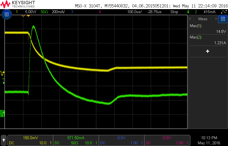
As is always the case with relays, there are nasty contact bouncing when looked at close enough. This switching may also cause short but high output voltage spikes. Figure below shows output when relay is turned on, and figure below that when there is 100 nF capacitor added at the output after the relay. Yellow trace is output voltage and green current.
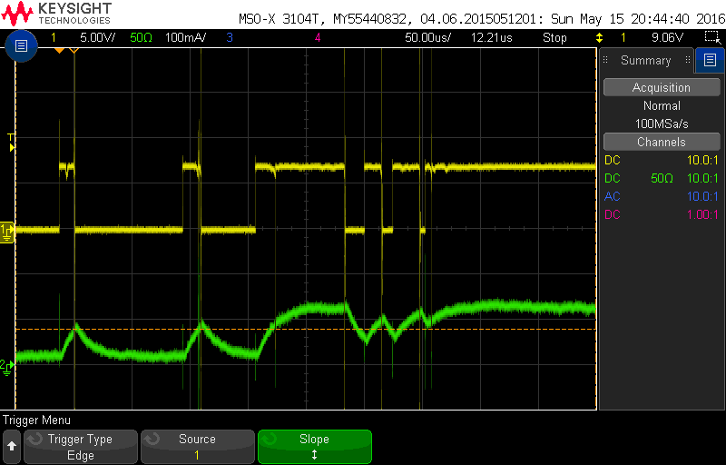

Capacitors clear the output a bit but bouncing cannot be easily avoided with relays.
Current limits
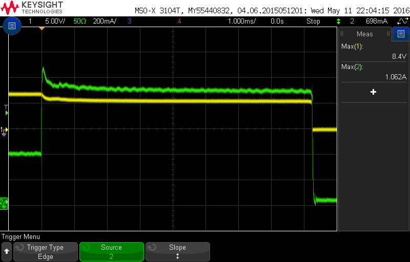
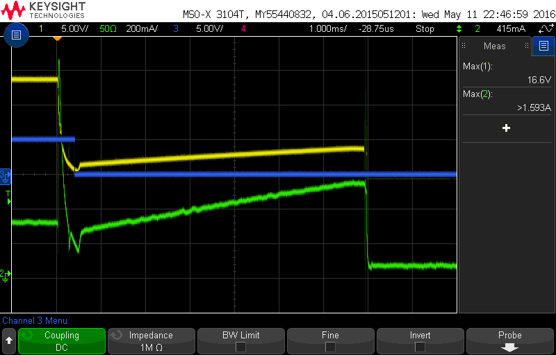
First I tested the software current limit by changing the output load so that current raises to a value above software limit but below hardware limit. Figure below (yellow is voltage, green current) shows the current rising from 400 mA to almost 900 mA (peaking at over 1 A). It takes over 8 ms for the software current limit to response and turn the output off – this is quite slow response time.
Next I increased the current step to be large enough for the hardware current limit to kick in. Figure below shows similar situation than above but now the hardware limit reacts almost immediately while it still takes 7 ms for the software to turn the outputs off.
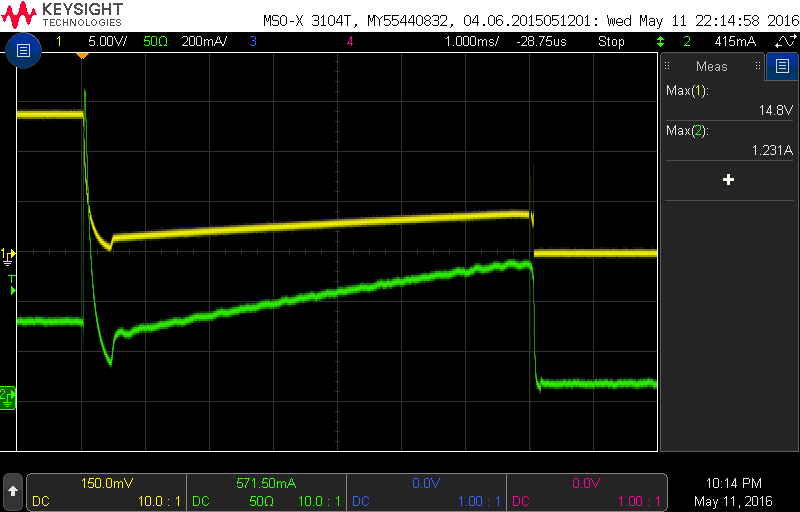
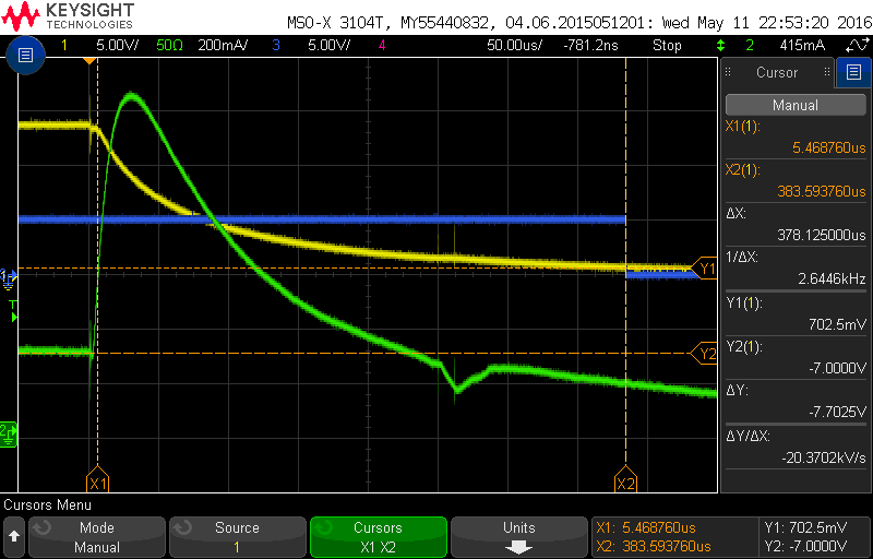
Below is the hardware current limit operation zoomed in (notice the difference in time scale).
Hardware current limit lowers the current in tens of microseconds while it takes 8 ms to turn off the relay. As this was new thing to me, the question was is it because of the slow software response or mechanical lag in relay? In figure below (and zoomed in below that), blue is the signal turning the relay off by going low. It can be seen that software actually reacts in less than 0.4 ms (which is still slow as well) but it takes another 6.5 ms for the relay to turn off due to its mechanical delay. This is a good proof that relays are quite useless as primary switches when it is necessary to rapidly limit current. Obviously this was not a surprise but now I have quantified it. Built-in hardware current limit is the actual protective element here, while relay prevents the error condition from continuing by disconnecting outputs.
See PSU Pre 2016 page for more measurements and fixes regarding mains switch noise and relay switch noise.
Files
v1.0A files in PDF
- Schematics
- Component placement top
- Component placement bottom
- Example software
- BOM
- Partly manually created so may contain some errors
- Not all components are necessary, especially if you do not use microcontroller
Version history
Schematics and PCB
- v1.0A Initial version
- Bugs and changes for next version
- U5 (5 V regulator for microcontroller circuit) is sourced from VDD but it should be VDD_UNR
- Now microcontroller resets if VDD dips, which usually happens at startup as hardware current limit kicks in when inrush current increases
- Also U5 does not even regulate unless VDD is higher than 5 V + dropout voltage
- See the text above for workaround mod
- Remove R24 (now 0 ohm)
- Silk screen changes
- Diode footprints are wrong way (because KiCad decided to swap diode pin numbers in version change!)
- Add a note on silk screen to only populate one of relay coil voltage resistors R40-R42
- Move name and version info next to P10
- Make better mark of pin 1 on SPI programming connector
- Change LED footprints
- Caps at the output and possibly other means to tackle relay contact noise
- Overvoltage protection components
- FT232RL Test pin should be connected to ground as per datasheet although few boards have been working with it floating
- U5 (5 V regulator for microcontroller circuit) is sourced from VDD but it should be VDD_UNR
This page
- 26.1.2017 Initial version
- 18.1.2018 Changed some wordings to emphasise output voltages and currents are fixed by resistor values and not controllable by firmware, and that microcontroller is not even required to use the board.
- 27.1.2018 Added BOM.
- 29.8.2018 Added info about FT232RL Test pin bug, also added text on the schematics
1 comment
[…] The Power-Supply which takes power from a RPT-75 power supply and stabilises the supply voltages for the op-amps and monitors all to voltage rails. It is based on Tomi's Smart PSU 3. […]
Comments are closed.