
Digital signal processor designed for my 4-channel DIY system.
- 6 digital stereo inputs: 2 toslinks, 2 coaxial RCAs, 1 coaxial BNC and AES/EBU (XLR)
- 4 coaxial BNC stereo outputs offering 8-channel output where channels are mixed/filtered from two input channels
- All electrical connectors are transformer-isolated
- Can be used for crossover filtering for multi-way active speakers, parametric equalisation, digital room correction; filters are given in parameters (PEQ), biquads and/or FIR coefficients; also includes level, delay, polarity, compressor/limiter
- DSP-solution from miniDSP: miniSHARC OEM/DIY-board and miniSHARC plugin software; outputs with CS8406
Note that this is one of my “old” projects and is kind of obsolete. I do have bare PCBs if someone wants but I have no intentions to further develop the design, documentation, or measurements, which are not really comprehensive. However, the device was fully functional so feel free to pick tips for your own implementation.
What is it?
SharcDSP is a multipurpose audio signal processor accepting stereo (does not accept coded multichannel formats) digital signal from any source. These 2 channels can be divided and mixed into maximum 8 separate channels where various filters can be added. Filter parameters can be set using PC by graphical interface with parameters or by pure coefficients, or even as a file exported from some acoustic measurement program such as Room EQ Wizard. I use SharcDSP for digital room correction (DRC), compensating effects of room acoustics, and subwoofer crossover filter but it could be also used as a DIY multi-way speaker crossover filter. Or any kind of audio IIR/FIR-filtering application fitting the computing capabilities of this particular DSP-solution.
The DSP board, firmware, and PC software (plugin) are not my design but by a Hong Kong based company miniDSP. I have no connection to them, I am just one of their customers, curious to take their products as part of my own designs to create impressive functionality with reasonable efforts. Therefore, I designed a motherboard for this DSP solution and packed everything into an enclosure.
Below are some screenshots of the plugin, a PC-software used to set up the filters and program the DSP. Therefore, no knowledge of DSP-programming or capacity limits are needed here. Here is the datasheet of the current plugin which determines technical capabilities of the DSP. New plugins may and most probably will be released. There are two versions of the same plugin for sampling frequencies of 48 kHz and 96 kHz.
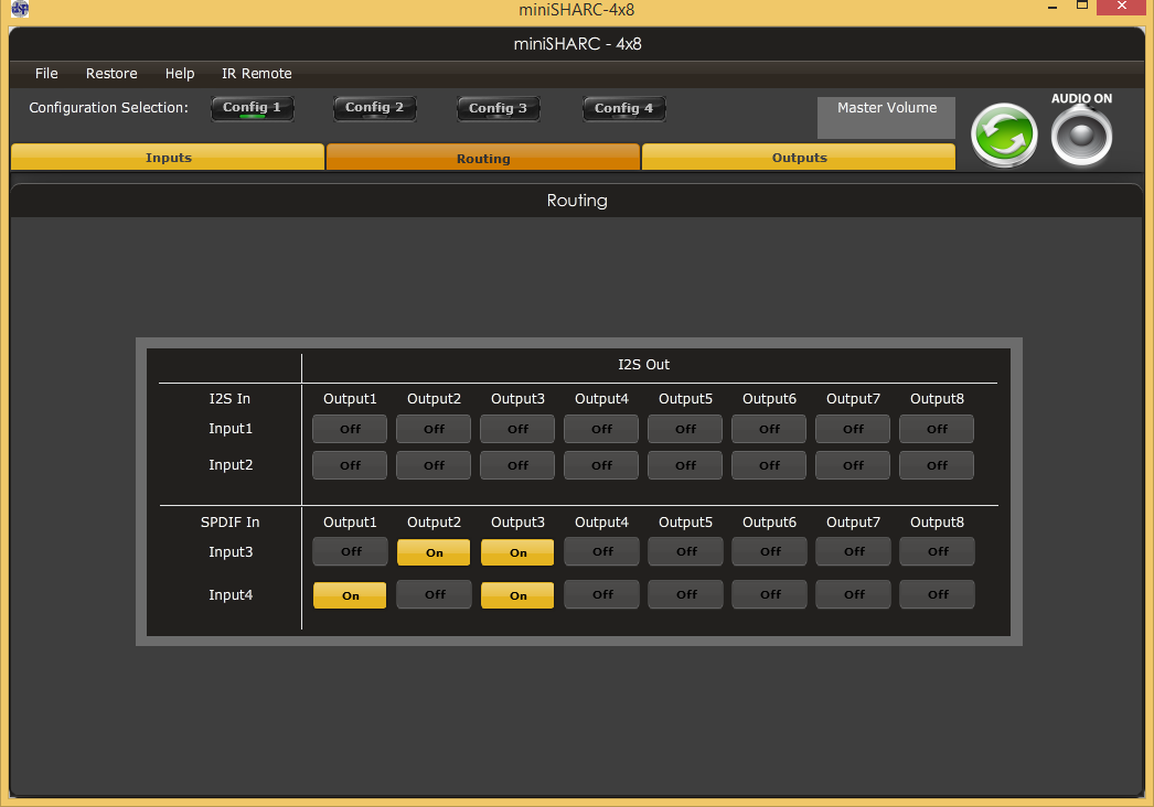
Minisharc plugin – mixer. Here channel routing is done. Output 1 and output 2 are left and right and output 3 subwoofer where both channels are summed (and filtered elsewhere). All settings can be saved into 4 different config presets which can be then changed without PC. I2S input is not used in this device.
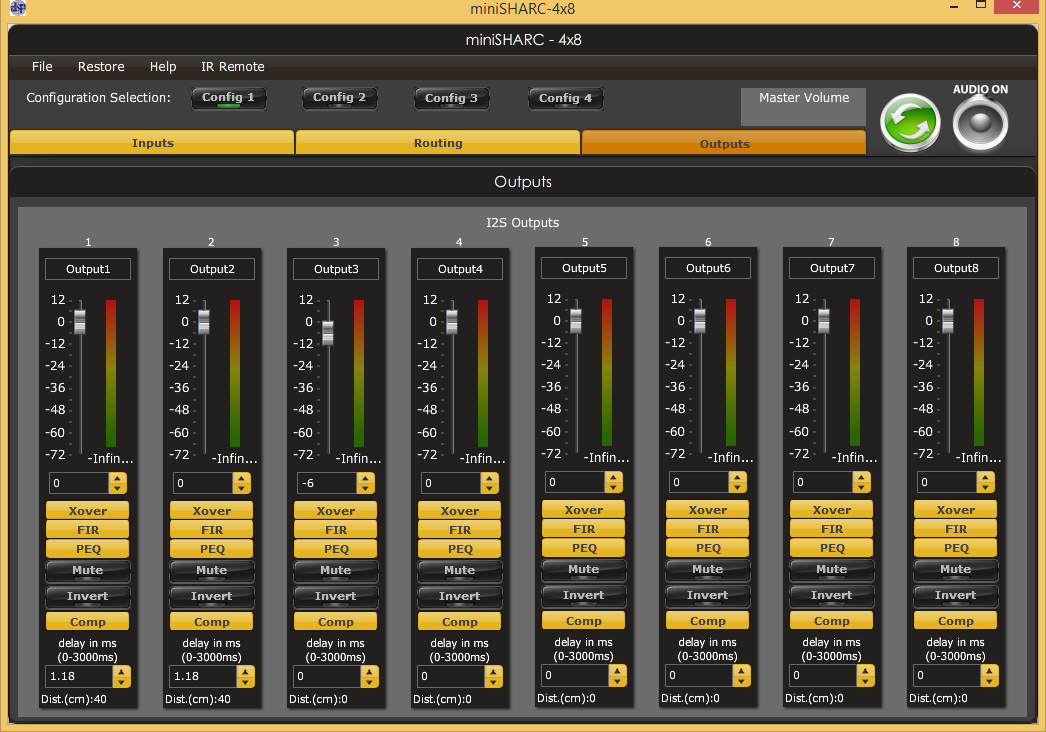
Minisharc plugin – outputs. Level, crossover, FIR-filter, parametric EQ, delay, etc.
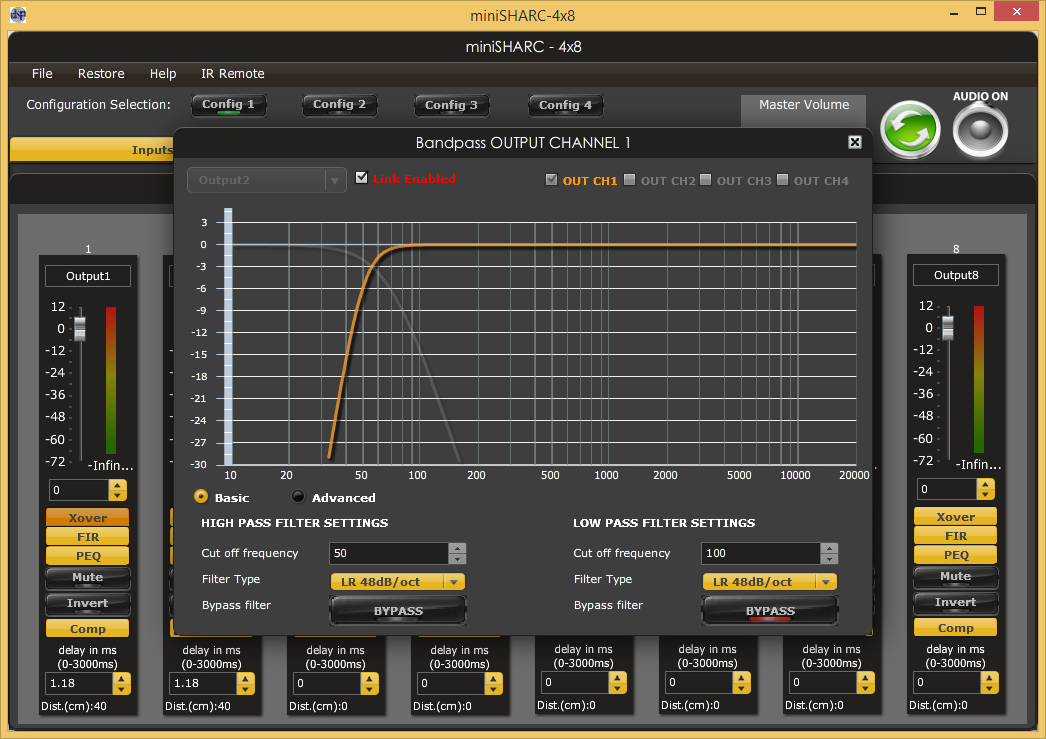
Minisharc plugin – crossover filters. Low-pass and high-pass filters can be added to channels, here high-pass for main channel. On the background can be seen setting panel for all channels including output level, crossover filter, FIR-filter, parametric/biquad, mute, invert, compressor and delay.
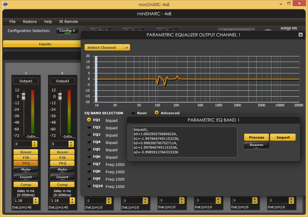
Minisharc plugin – parametric eq / biquad. Filters can be set up by parameters or importing coefficients. Here filter coefficients are from Room EQ Wizard for digital room correction.
The rest of the page is related to my own design, the board I designed for the miniSHARC.
How does it work?
This SharcDSP board I have designed acts as a motherboard for the miniSHARC which has Analog Devices Sharc ADSP21369 signal processor along with clock oscillator, stereo SPDIF input with sample rate converter and I2S interface for 8 output channels. The functionality my board provides, despite making the DSP to work, is to change the input and select DSP filter configuration out of 4 stored presets. There is also a wired remote functionality so that my DIY preamp can control the input and preset. Below is a functional block diagram.
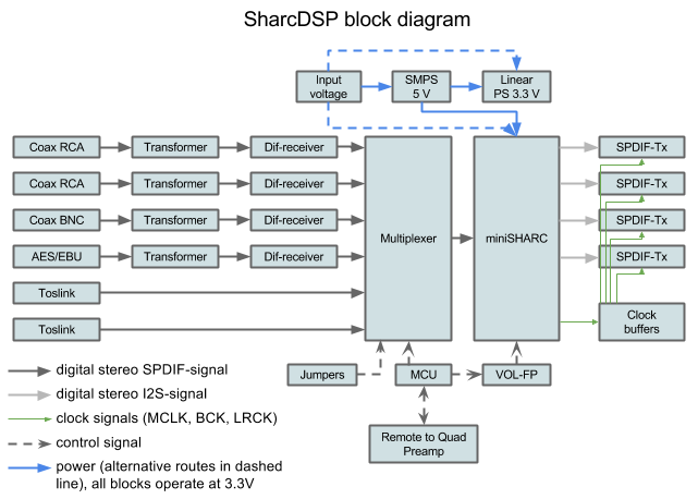
Digital inputs are routed to multiplexer for input switching, electrical signals through isolation transformer and differential line receiver. SPDIF-signal is fed to miniSHARC which has SPDIF-receiver and sample rate converter. I2S outputs are routed to SPDIF-transmitters along with 3 different buffered clock lines (master clock, bit clock and word clock). Input selection can be done by jumpers but microcontroller (MCU) is used for wired remote control functionality with Quad Preamp and for DSP filter preset change via VOL-FP add-on board. Device is powered from AC-wall-wart. Power distribution network is not drawn.
Schematics
SharcDSP schematics can be seen here. It is drawn with Kicad and has hierarchical sheets. First page is top level and blocks labeled “Sheet: name” are shown on following pages. Pin-like connections in blocks are hierarchical labels going between hierarchical levels or pages. Power labels are global throughout the document.
Basis for the design is the miniSHARC and its pin header P1. DSP has its own clock oscillator and external one cannot be used, unlike with some other miniDSP boards. Therefore, this master clock (MCLK) as well as bit clock (I2S_BCLK) and word clock (I2S_LRCK) are taken from miniSHARC, buffered (CDCV304; IC1, IC2, IC3) and along with data fed to 4 stereo SPDIF-transmitters (CS8406; IC4, IC8, IC9, IC10) to provide the 8 output channels. If I2S (inter-IC sound) is not familiar, information particularly with these products can be found here. Briefly, it has 3 signals: data, bit clock, word clock and usually the ICs operating also need a master clock which is some integer multiple (eg. 128x or 256x) of sampling frequency.
CS8406 SPDIF-transmitters are configured for 48 kHz input signal. With jumper (P4, P13, P15, P17) it can be changed to 96 kHz if miniSHARC-plugin/firmware is changed to one requiring that. Other IC configurations set some flags in the SPDIF-signal and more info can be found in CS8406 datasheet. Output is 75-ohm SPDIF with transformer (PE-65612) isolation and BNC connectors. I wanted to put BNC just because of their superiority to RCA and because they give better impression. After all, the DAC is also my design with BNCs so “non-standard” cable is not a problem. And BNC-RCA adaptors can be used anyway when needed.
Red PCB is the one I have designed and blue on top of it is a miniSHARC kit from miniDSP, the actual DSP board. The small blue board is a miniSHARC add-on board whose functionality is explained in Changing presets -section. The designed motherboard provides all the necessary connections and control for miniSHARC.
Input selector
Input selector has two RCA/Toslink combo connectors (P6, P7), BNC (P8) and a connector for panel-type XLR (K1) for AES/EBU. Toslinks are 5 V so they are fed through 74LVC125 (U1) buffer operating at 3.3 V. All electrical signals use isolation transformers (PE-65612). From RF-interference point of view isolating of connectors may not be a good idea. I have provided a place for capacitor from shield to ground, close to the chassis connection. However, to be effective this should be directly on the connector which may be difficult to implement. Signals are terminated by 75 ohms except AES/EBU 110 ohms. Diodes to rail (BAV99) are provided for protection.
Differential signals are inputs to DS90LV028 (IC5, IC6) line receiver. Signals are biased using component network (L11, R58, C20, C19, R59) to provide approximately 1.4 V voltage. This should provide enough headroom for the line receiver in all circumstances. All single-ended input signals are fed to multiplexer (74HC151; IC7) which is the actual input selector. This is controlled by 3 control lines. These can be routed from microcontroller or other external logic or controlled by mechanical rotary switch using pinheader P9. Thus, microcontroller (ATmega168A; IC11) and its external components can be omitted. In this particular unit they are used for the wired remote control with the preamplifier.
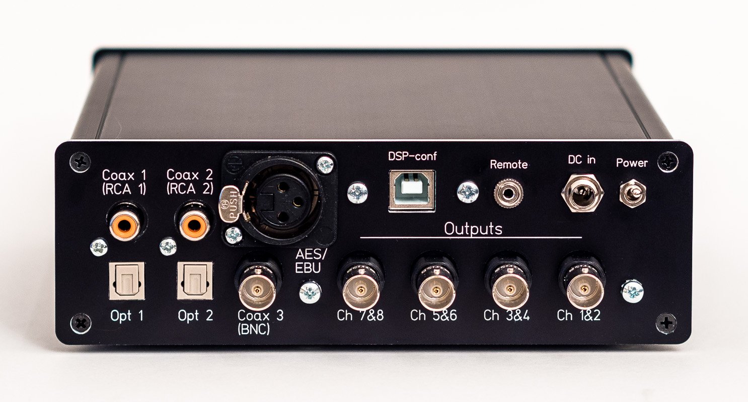
Rear panel is packed with connectors for digital signals: 6 stereo inputs (2x RCA, 2x Toslink, BNC and AES/EBU XLR), 8-channel output as 4 stereo BNCs, USB for DSP configuration and remote control with my DIY preamp.
Power
Unlike other components in this 4-channel system, SharcDSP doesn’t have a mains transformer but is powered from wall DC-adapter. Power supply consists of 5 V and 3.3 V parts. There is a switched-mode power supply (LM2675; U3 and its external components) so input voltage can be in quite wide range. The component values have been chosen for 12 V. It is also possibly to feed the system with 5 V and omit the switched-mode power supply completely. Supply for the miniSHARC can be chosen from input or 5 V – it has its own switcher anyway. With certain ferrites (or 0-ohm resistors can be used) it is possible to choose different powering schemes. TPS77633 (U2) is used for 3.3 V regulation.
I am also using ferrite beads with capacitors for ICs throughout the design. They can help from EMC point of view and they also act as bridges for layout design since I’m using only 2 layers. Also 0-ohm resistors can be used, however, ferrites are cheap.
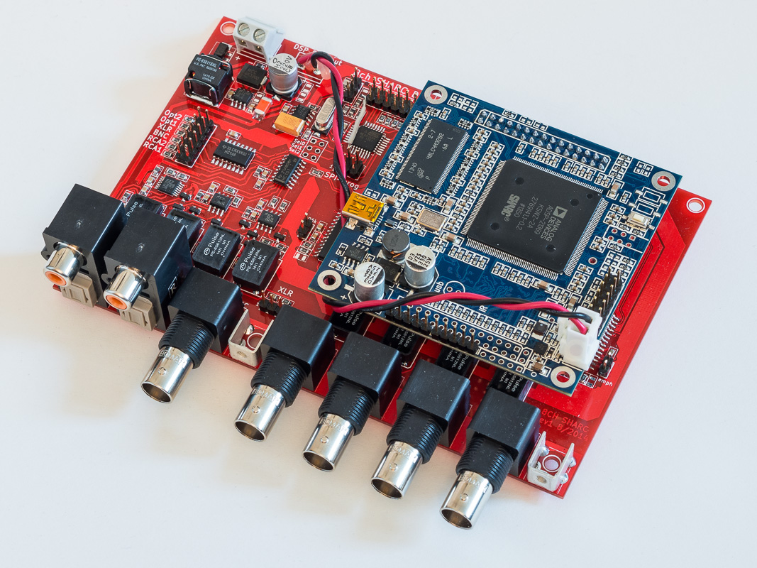
My SharcDSP board and miniSHARC by miniDSP.
Layout
Board is 2-layer and measures 15 cm x 10 cm, I also wanted to try colourful mask for the first time so that’s why it is red. Main point for layout is to have a place and connector for the miniSHARC. I made a small mistake here and forgot to add the screw connectors for the board on the opposite side of the pin header. From the pin header there are clear paths for all clocks and data with plenty of ground around and at close proximity. SPDIF transmitters, transformers and BNC connectors are on the lower edge. There is also an area of ground on both sides of the PCB which is connected to enclosure with screw connectors, thus acting as an extension for the enclosure and area where signal ground and other ground connectors are connected to.
The rest of the edge is populated by input connectors except AES/EBU which is wired non-PCB connector due to lack of space. This side of the board is more dense with input signal receivers and routing to the miniSHARC pin header. Power supply is immediately after power connectors and microcontroller circuit where there was some space left.
I have not been able to do any EMC measurements but have tried to design the board as good as I can with my current skills and with 2 layers. PCBs are from Iteadstudio.
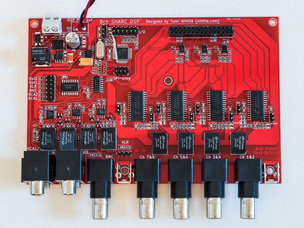
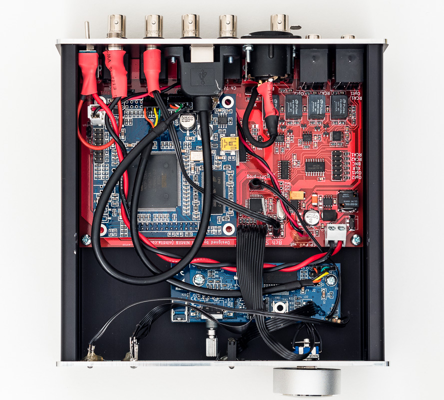
SharcDSP board. That one wire is just to connect one extra pin of pin header to the microcontroller. Microcontroller is not necessary for operation but here it provides wired remote control functionality with my DIY preamp. All digital audio connectors are isolated with Pulse transformers.
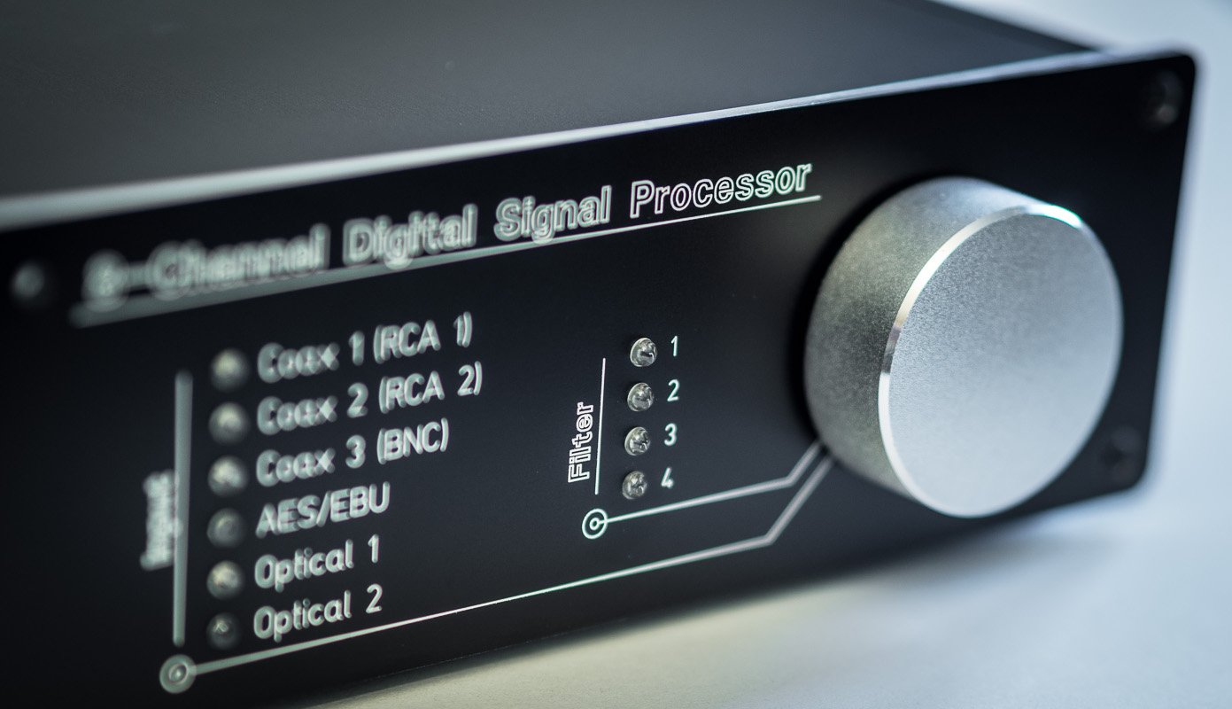
Enclosure
Basic enclosure is from Hammond, measuring 160 cm x 160 cm. However, what makes it stand out are the custom made front and rear plates from Schaeffer AG. This mechanical design also took a lot of time but the result is excellent, it doesn’t even look DIY anymore. These plates are not cheap so you want to triple-check that every hole is where it should be.
miniSHARC board
miniSHARC is a multi-purpose audio digital signal processor (using Analog Devices Sharc ADSP21369) which can be used in various filtering tasks in audio such as multi-way active speaker crossover filtering and equalisation. I am using it for digital room correction which is equalisation based on the characteristics of the audio system including room acoustics. These DSP boards by miniDSP Ltd are for OEM applications and custom products, therefore most of the products they sell cannot be used on their own. It is also the case with miniSHARC – it is a bare PCB without connectors and with interface you cannot find in commercial audio products. It needs a motherboard to provide needed connections, which is what I have done here. It accepts uncoded stereo (no coded multichannel formats) SPDIF input (but directly from coaxial RCA which has wrong signal level) but output is I2S which is a synchronous serial digital audio format with data and 3 clock signals. There are 2 input channels but 8 output channels so the input channels can be divided into various outputs with various filters.
Setting up DSP is programming all needed filters along with level, delay and compressor if needed. Filters can be set in parametric format (PEQ), biquad coefficients or FIR coefficients. These are done in PC-software, or plugin as they call them, so computer is always needed when setting up the DSP. 4 configuration sets can be stored and these changed also without PC. For digital room correction, acoustic measurements are necessary. I am using Room EQ Wizard (REW) software and UMIK-1 USB measurement microphone for measurements, and from REW you can export filter parameters and import them into the plugin. It is an iterative process of measure, setup, measure, listen, etc. MiniDSP website has some application notes for DSP-basics, digital room correction, acoustic measurements and how to get quickly started with REW. I have mostly followed these to get started. I am not an expert in this field yet and have a lot to learn and experiment when all my hardware is finally finished.
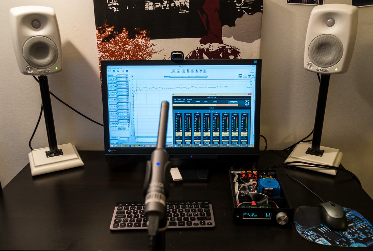
UMIK-1 USB-measurement microphone is used for acoustic measurements with Room EQ Wizard (REW) software. Based on the measurements, filters are computed in REW and imported into the plugin. The point is to measure response at the listening spot and set up filters to compensate (the worst) deviations from the desired response (which is not necessarily flat).
Changing presets
There is a possibility to save filter sets as presets in miniSHARC PC-software and then later change the active presets without PC. However, to do that it is required to have VOL-FP add on board which provides rotary encoder and IR-receiver. By using IR, generic remote controller with NEC or Sony codes can be used to teach the commands to miniSHARC with the PC-software. Besides some other functions these commands include preset-changing. What I have done, is to remove the IR-receiver and wire a microcontroller pin to that. Then, by imitating NEC IR-codes the microcontroller is able to change presets in miniSHARC. Not very elegant but much easier to implement than reverse-engineering the 2-way custom communication protocol (according to miniDSP) between miniSHARC and VOL-FP.
Having said that, the preset-changing implementation kind of works but it is a bit laggy, cumbersome, and does not work every single time.
It is possible to save 4 filter bank configurations in miniSHARC. PC is required to program the filters but presets can be changed within SharcDSP.
Version history
The device
- No changes since initial version. This is now obsolete. I do have bare PCBs but I have sold my only fully populated board.
This page
- 24.11.2014 Initial version
- 5.1.2017 Re-published in new website design and added a note on top.
4 comments
Hi. is it possible to buy a SharcDSP kit?
IT’S PERFECT FOR MY SYSTEM
Unfortunately there are only a few old bare PCBs left.
Hi. Are bare PCBs still available for sale?
Unfortunately no PCBs left anymore.
Comments are closed.