
- Very high performance
- THD+N ratio: -108 dB (1 kHz -5 dBFS)
- THD ratio: -115 dB (1 kHz, -10 dBFS)
- Dynamic range / SNR: 119 dBA
- Crosstalk: -125 dB, 10 kHz
- Comprehensive measurement data available
- Unbalanced RCA, 2 V output level
- Balanced addon available
- I2S input, supports up to 32 bits and 768 kHz sample rate
- 5 digital filters selectable with jumper links
- AK4490EQ DAC, LM4562 opamps
- Compact size at 70 mm x 50 mm
- Can be used with any compatible I2S source or in Wee DAC system
- Wee DAC ecosystem offers numerous compatible boards
- Balanced XLR addon
- S/PDIF input boards (Coax, Toslink, AES/EBU)
- Baseboards with or without power supply
- Assembled boards available
W-DAC was designed as part of Wee DAC ecosystem but it can be used in any system providing needed supplies and compatible I2S signals. By using other Wee DAC boards, complete DAC with extensive digital input options as well as balanced XLR outputs can be built.
Below is a 2-page factsheet (PDF) showing key figures and features.

Notes on naming: Wee DAC refers to this whole system of DAC board, S/PDIF input board and other addon boards, while W-DAC refers to this DAC board. 4490 on the name refers to the DAC chip used; there will be other versions as well from which higher spec W-DAC 4493 uses the same PCB but different DAC and regulators.
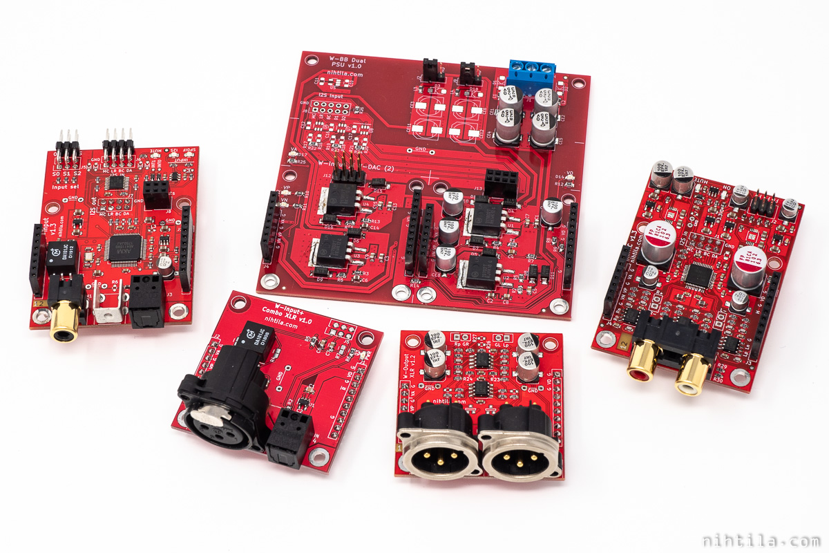
Wee DAC system
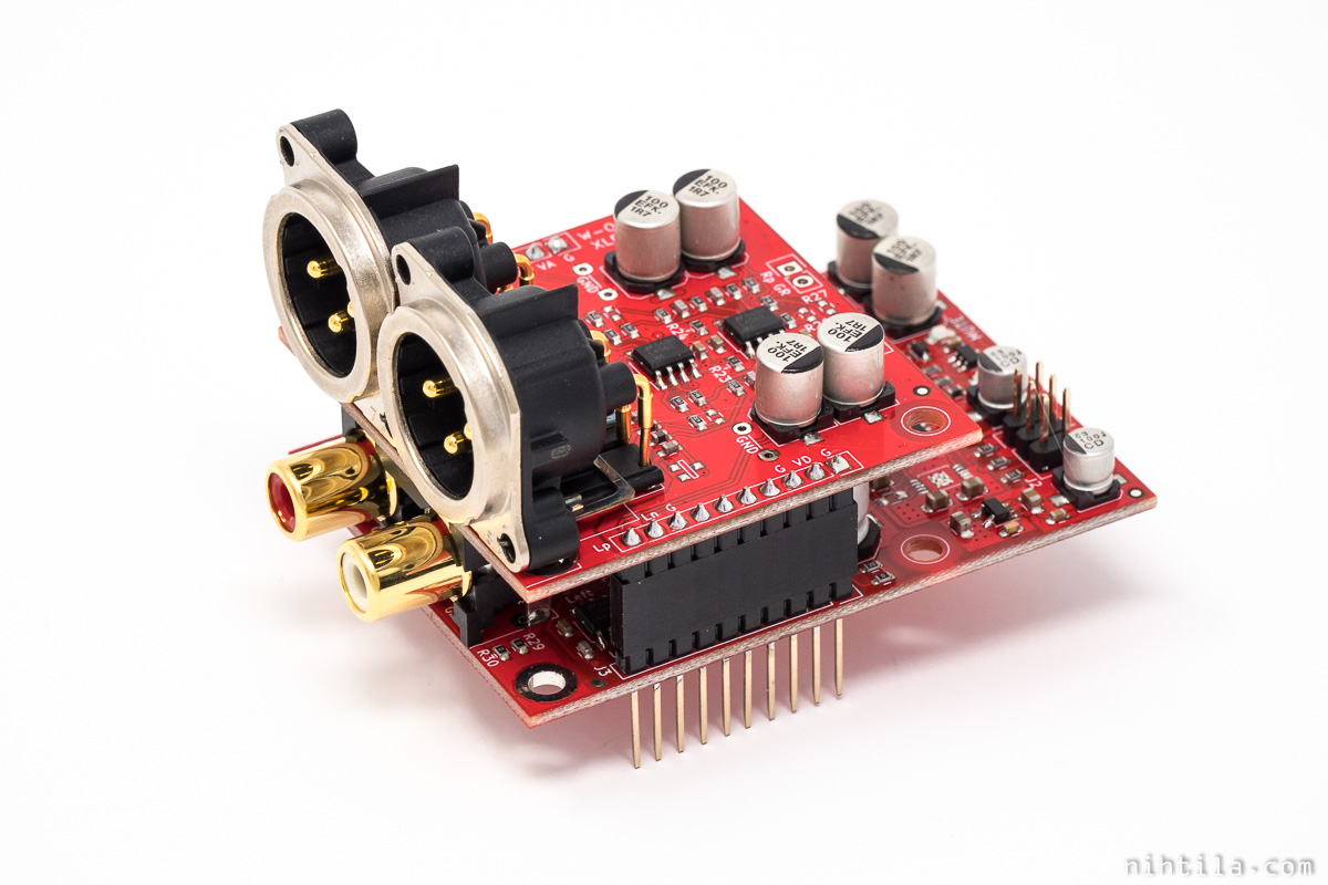
W-DAC with W-Output XLR balanced addon
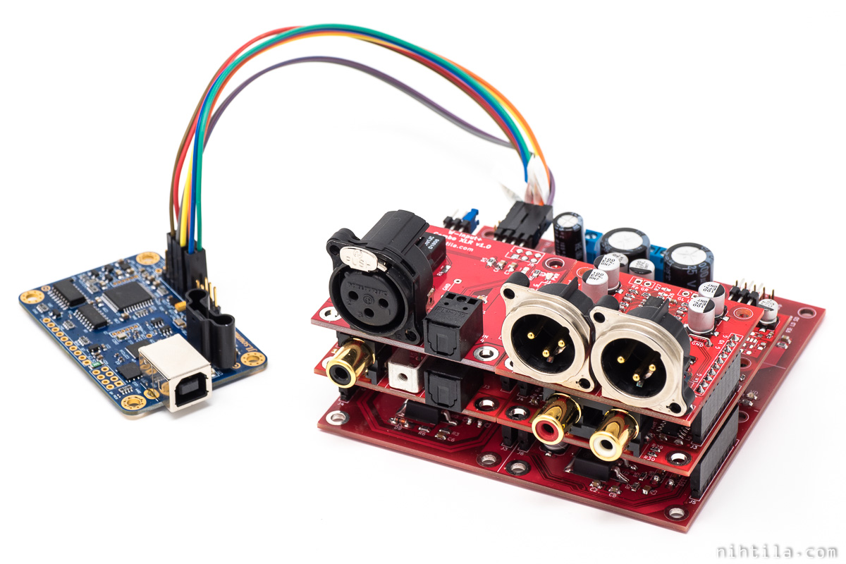
W-DAC used with other Wee DAC boards and JLSounds USB module
Extensive amount of measurement have been carried out on a few different prototypes when developing this DAC, using state of the art measurement kit.
Design
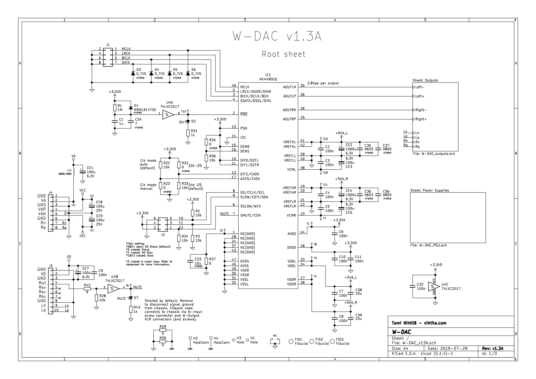
As this is still more hobby than a side business and I have learned a lot by investigating others’ schematics, I have decided to release W-DAC schematics. I won’t go into great detail of each component and approach for now but some development can be found in Wee DAC update posts. There also may be slight changes due to last minute tweaking or production reasons.
Note that A-version is this AK4490 and B-version is upcoming higher spec AK4493 version.
First of all, the role of W-DAC in a complete DAC system (whether it’s Wee DAC or something else) can be illustrated in Wee DAC block diagram below. Basically it has an I2S input, a DAC, and an output stage.

W-DAC highlighted in Wee DAC system diagram
DAC
DAC IC and its passives can be seen below. There are great number of capacitor placeholders as it was clear from the development that this DAC is sensitive to power supplies, especially analog references. However, not all these caps are populated. More is not always better and used voltage regulator along with caps has huge impact on performance. It is a combination of trial and error and extensive measurements.
AK4490 has 5 V analog supplies, 3.3 V digital supply plus additional 3.3 V analog supply. It’s crucial to use onboard regulators. Raw voltage supplies are brought via Wee DAC headers that are common to all Wee DAC boards.
These AK DACs are also quite strict when it comes to reset, therefore delay reset circuit with schmitt-trigger is used. Sometimes longer reset delay is required (depending on how quickly supplies are up), this can be done by adding more capacitance to C1/C34.
External mute signal is used so that W-Input board can mute the DAC when required.
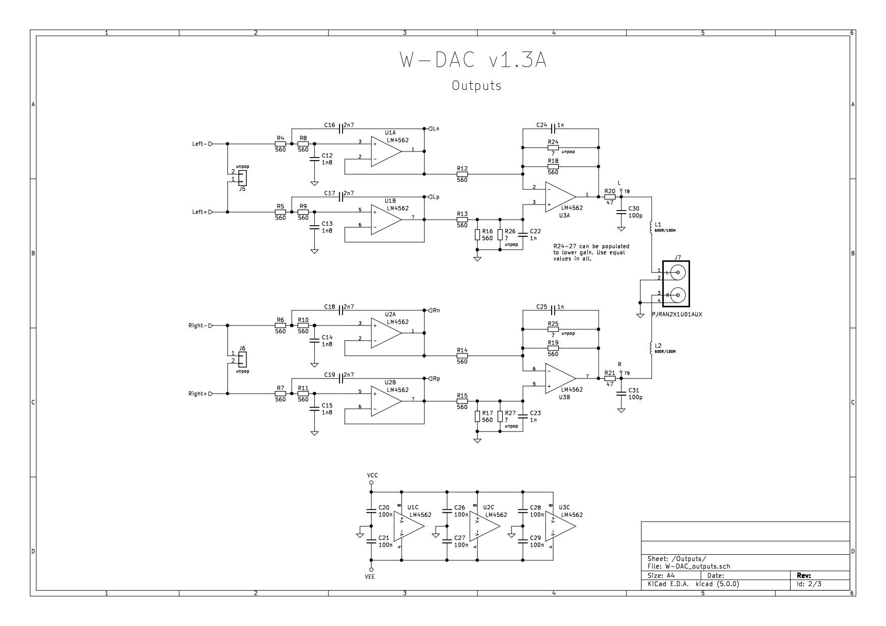
Outputs
Output filter is a rather straightforward opamp-based filter. It is a third order Bessel(-ish) with a cutoff frequency around 100 kHz. Each of the four DAC voltage outputs go through a second order Sallen-Key filter followed by differential amplifier with another low-pass stage.
Low resistor values have been used to gain low noise but it also means burning significant power at the output stage. This doesn’t really matter but the board does get warm.
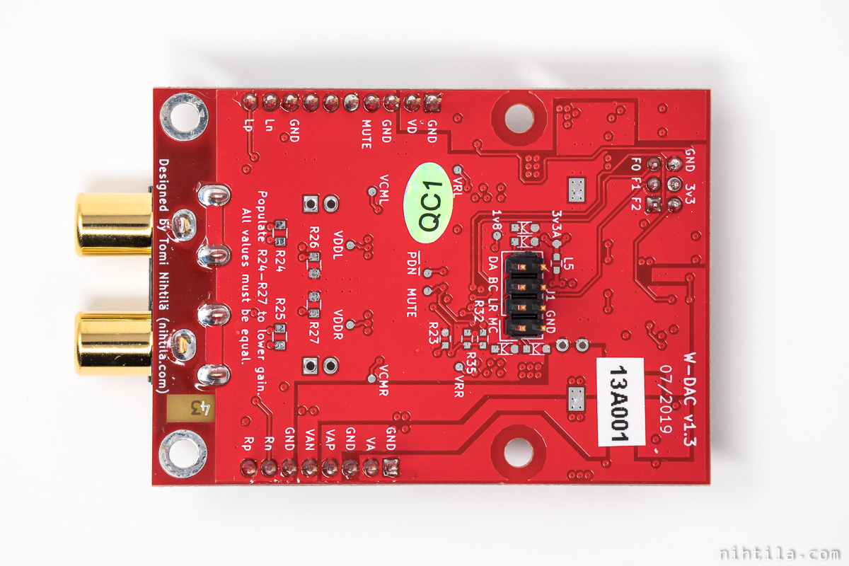
There are additional parallel resistor placeholders on bottom side of the PCB to lower gain if needed; these are the unpop resistors at the differential stage.
Points Ln, Lp, Rn, and Rp are brought to Wee DAC pinheaders to connect to Balanced XLR addon board.
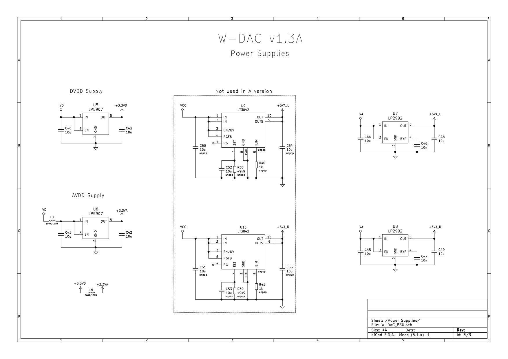
Power supplies
Input supply VD is 5 V supply that is used to generate 3.3 VD and 3.3 VA using LP5907 regulators.
LP2992 regulators are used for 5 VA which is used by VREF and VDD supplies of the DAC. Input supply is VA which in Wee DAC power supply boards is around 7.2 V. It’s not strict; LP2992 can take up to 16 V although it cannot handle much power so it’s better to keep it closer to 5 V than 15 V. LP2992 is an impressive regulator for its low price, especially noise performance is great.
LT3042 is used instead of LP2992 in the higher spec upcoming W-DAC 4493 model.
Output pops and clicks
A few words’ disclaimer on output pops and clicks, meaning unwanted glitches when turning power on or off.
W-DAC does not have output mute circuit!
DAC with an external output circuit without external mute will always generate some unwanted pops; even if DAC IC is quiet, opamps will not be. This is not a complete product so it is always end user’s responsibility to protect their speakers, headphones, and ears from potentially harmful pops and clicks. Power amplifier or headphone amplifier should have a mute circuit included.
A circuit that delays power-on but is fast at power-off is typically enough; usually power amplifiers have this. This should work even when turning the whole system on/off simultaneously. For example, I have an extension cord with switch that powers my whole system at once, including headphone amplifier, subwoofer power amplifier, and active speakers – there are no pops at all on any of these.
More details on W-DAC pops
When AK4490 comes out of reset, it produces a very loud pop. This happens at power-on but also if I2S clocks are lost and re-applied.
There is a major difference between AK4490 and AK4493 (in the upcoming higher spec W-DAC) in terms of pop and click behaviour, as AK4493 does not produce pop when clocks are lost and re-applied. This just means that when using AK4490, ensure clocks are continuous at I2S source (which should be the case anyway).
Extra care is required when using W-Input board with I2S input, as if I2S input is selected but nothing is connected to that input, clocks are lost and AK4490 goes to reset state. This never happens with S/PDIF inputs as there are always clocks.
There is not really audible pop when W-DAC is turned off.
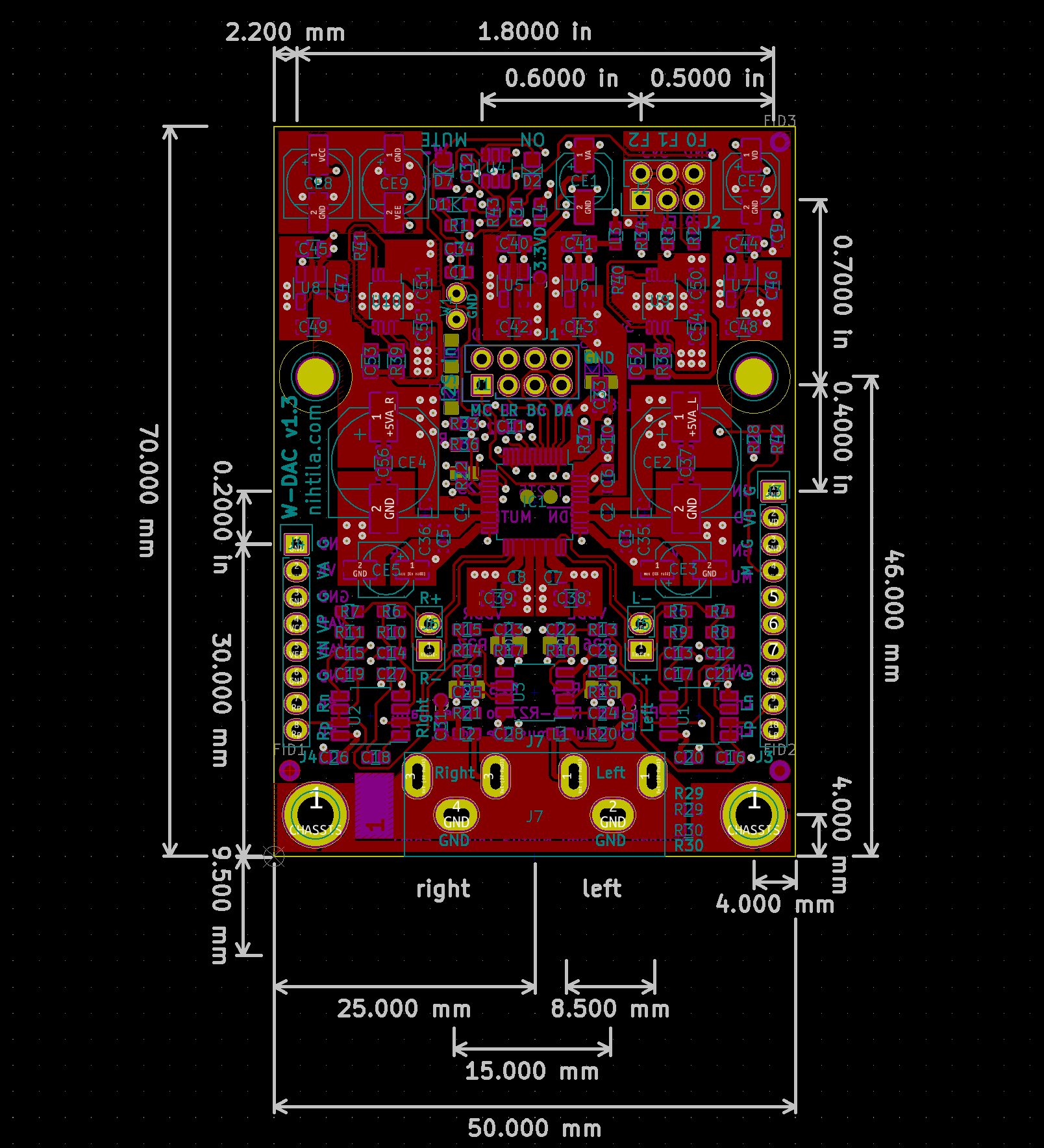
PCB
PCB is 50 mm x 70 mm 4-layer board. PCB is one of the most important components of any design and in order to achieve great performance in such a small form factor, 4 layers are minimum.
Schematics and layout have been done with KiCad and components sourced from Mouser and Digikey. PCBs are from Elecrow.

Configuration and settings
AK4490 is used in hardware/parallel mode so audio is active just by providing supplies and correct I2S signals.
Supplies
Supplies are provided on edge Wee DAC pinheaders. Note that there is no protection against over-voltage or reverse voltage; if you are unsure connecting please use a dedicated Wee DAC baseboard.
Required supplies and rough current consumption are as follows:
- VAP: +15 V, 37 mA
- VAN: -15 VA, 32 mA
- VA: 7.2 V, 22 mA
- VD: 5 V, 9 mA
±15 VA are used for opamps so it’s not very strict. I wouldn’t go higher due to excess power consumption but it can be lower. 7.2 V is the value for VA in Wee DAC baseboards but it can be something like 6-9 V; if going higher it’s worth checking tiny LP2992 regulators can take the extra heat.
VD cannot be higher than 5.5 V due to LP5907 limit.
I2S input
I2S signal is routed directly to AK4490 DAC. While the DAC supports great range of PCM formats, here it is fixed to I2S which is the most commonly used one. Default is 24-bit I2S but this can be changed to 32-bit by soldering resistor R32. However, 32 bits does not bring anything extra in terms of dynamic range.
I2S signals are provided on 2×4 pinheader and signals marked as MC (MCLK, Master Clock), LR (LRCK, Word/Frame Clock), BC (BCLK, Bit Clock), and DA (Data). By default these lines have no protection so please ensure signal level is correct 3.3 V.
For more details on supported I2S format, please refer to AK4490 datasheet.
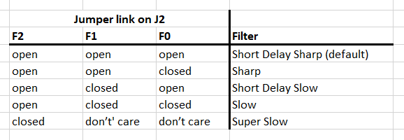
Digital filter setting
Really the only setting for user is digital filter, provided by pinheader J2. There are 5 digital filters in AK4490, named in the datasheet as follows:
- Sharp
- Slow
- Short Delay Sharp (SD Sharp)
- Short Delay Slow (SD Slow)
- Super Slow
Find the characteristics in the AK4490 datasheet.
Filters are selected by closing jumper links F0-F2, marked on PCB. Default filter is SD Sharp which is selected if no jumper link is placed on J2.
If the end system has a microcontroller, digital filters can be selected using digital I/O as well.
LEDs
There are two LEDs, On and Mute. On LED is lit when DAC IC is not on power down or reset state. Mute is lit when external Mute signal is active.
Measurements
Extensive amount of measurements have been carried out on various prototype phases. At the end of the process several boards have been measured and correlated to ensure consistent performance. That being said, these specs are not guaranteed but represent typical values for the design. However, every board will be individually measured and if there is large deviation, it goes under investigation to fix or discard it. Moreover, some boards also perform better than the specs given.
Measurements have been carried out using Audio Precision APx555 audio analyser. Unless otherwise mentioned, measurement bandwidth is 20 kHz and frequency in single-tone measurements is 997 Hz.
W-DAC is powered by a W-BB Dual PSU connected to bench power supply.
Default filter Short Delay Sharp was selected in AK4490.
Output level
Maximum output, 0 dBFS level is 2 Vrms / 6 dBV.
Output stage is DC coupled so there are no capacitors on signal path. Therefore, there can be a small DC level at the output. Typical DC offset is -3 mV.
Dynamic Range / SNR
Unweighted SNR is 117 dB and A-weighted SNR 119 dB. A-weighted dynamic range is the same 119 dB.
THD+N and THD
Figures are given for the sweet spot and for 0 dBFS. Knowing sweet spot is important if DAC is used for measurements. There is no intention to hide anything – full sweeps are shown as well.
THD+N, 997 Hz
- -5 dBFS: -108 dB
- 0 dBFS: -106 dB
THD, 997 Hz
- -10 dBFS: -115 dB
- 0 dBFS: -107 dB
THD+N vs. amplitude
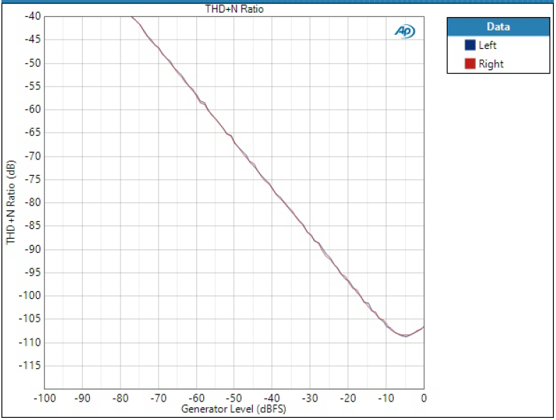
THD+N vs. amplitude, 997 Hz
THD vs. amplitude

THD vs. amplitude, 997 Hz
THD+N vs. frequency
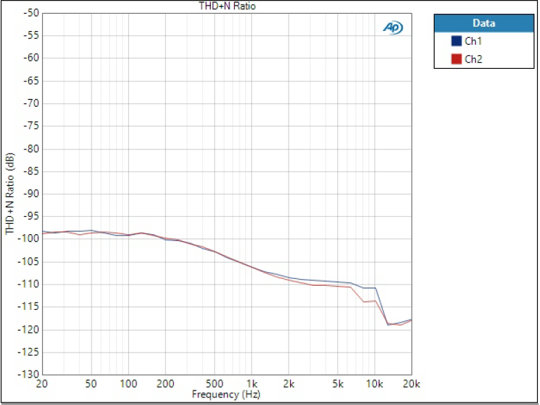
THD+N vs. frequency, 0 dBFS
THD(+N) conclusions
At high signal levels THD+N almost equals THD which is typical – distortion dominates noise at high signal levels. It’s interesting though that THD+N and THD have quite different sweet spots. It’s not unusual for DACs to have sweet spot lower than 0 dBFS.
THD increase at low frequencies is somewhat a weakness of this design. It is somehow related to VREF supply. Higher spec W-DAC 4493 with better voltage regulator has a flat THD+N vs. frequency plot. It is worth noting though that it is not common to even see this information on commercial DACs and in practice this is likely more important in measurement applications where flat THD+N is preferred.
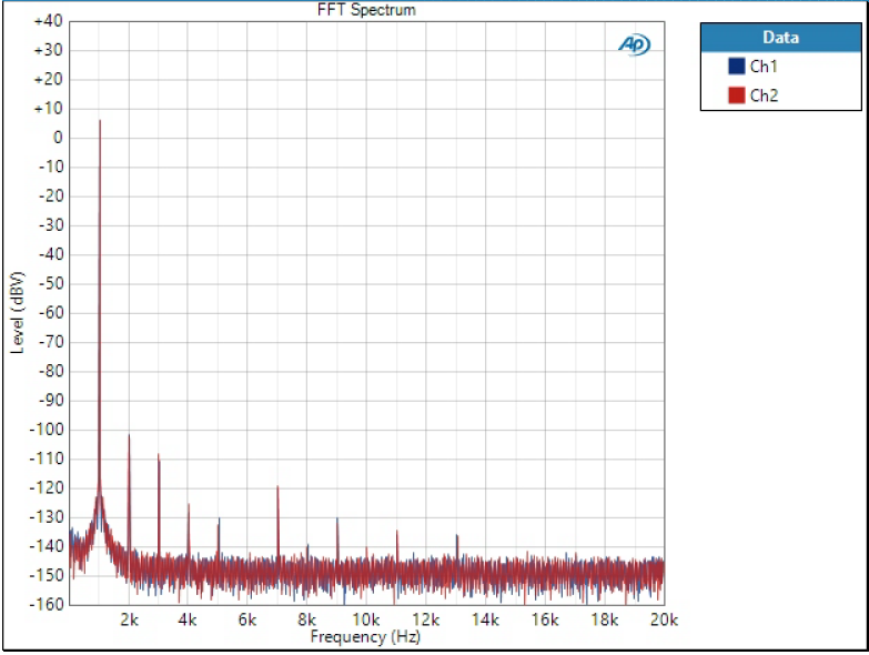
FFT
FFT 1 kHz 0 dBFS
FFT is given at 0 dBFS level to show the worst case.
High bandwidth FFT without signal
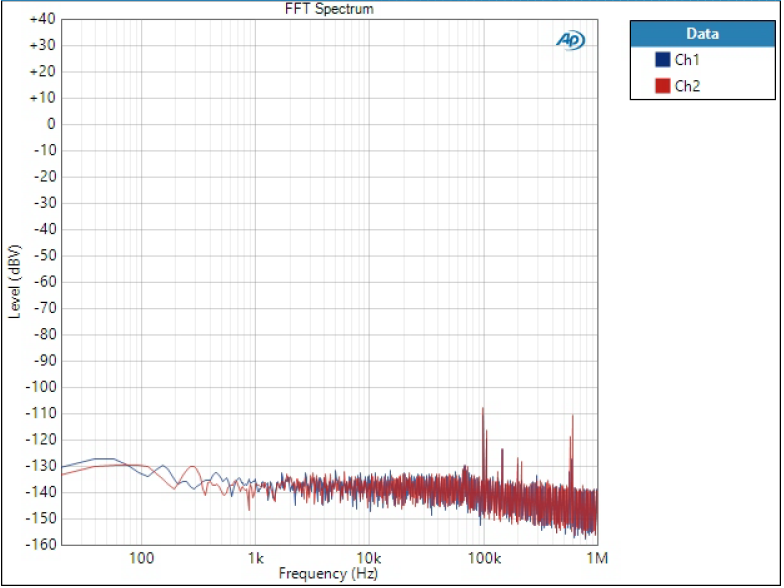
FFT without signal
Frequency response
Slight increase at 20 Hz is due to measurement filter. Slight roll-off at 20 kHz is due to analog filter starting to attenuate. Recall the scale though; this attenuation is only around 0.2 dB. Phase is not shown but it’s around 20 degrees at 20 kHz.
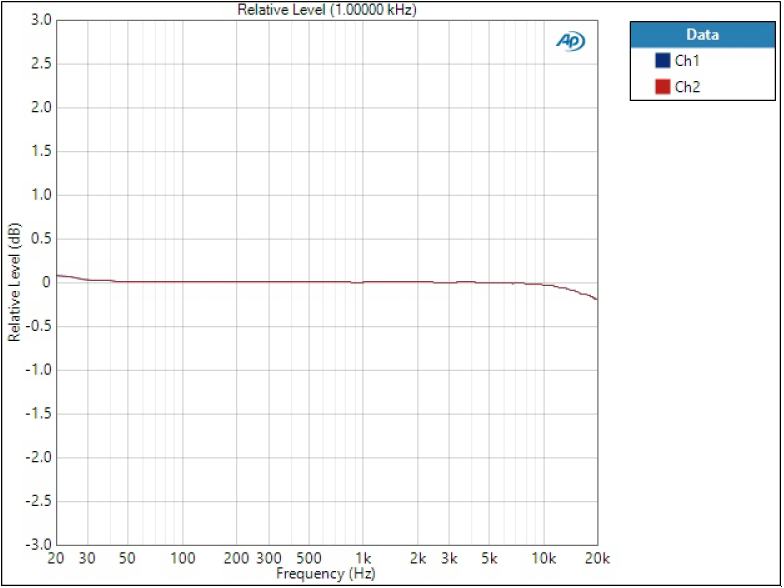
Frequency response
Crosstalk
Crosstalk at 10 kHz is typically lower than -125 dB.
Digital filters
Digital filter determines time and frequency domain behaviour of the output signal. One can choose to optimise time domain or frequency domain, or go somewhere in between; however, there is always a compromise between the two.
Detailed measurements of digital filters options of AK4490 are presented in a separate post so I will not copy them here: DAC digital filters part 2 – deeper dive into AK4490 and AK4493 filters
If you don’t know, understand, or care about digital filter selection, sticking to the default SD Sharp is a good option.
Files
I’ll do my best to keep these files up to date if something changes but there is no absolute guarantee. However, these do represent a working v1.3A initial release so there won’t be major changes.
- v1.3A files
References and additional information
- 2-page factsheet
- Wee DAC system
- AKM AK4490EQ datasheet
- DAC digital filters part 2 – deeper dive into AK4490 and AK4493 filters
- DAC digital filters and their impact in time and frequency domain
- Understanding audio measurements: THD+N vs. amplitude and frequency
- Understanding audio measurements: noise, SNR, and dynamic range
Version history
Schematics / PCB version history and known errors and bugs
- v1.3A First released version
This page version history
- 5.11.2019 Initial version
- 27.2.2020 Added factsheet
I may have missed something important here. If you have more questions about this board, please comment below or send an email.
Buy W-DAC here.