
Simple USB audio interface for headset
- Based on PCM2912A reference design; single IC providing:
- USB-interface
- 2-channel DAC and headphone amplifier
- 1-channel ADC and microphone bias
- TRRS jack for headset, or headphones and microphone can be wired out separately
- CTIA or OMTP type jack can be selected with jumper link
- Not for higher end audio but perfectly adequate for gaming, podcasts, calls, etc.
This project was quickly born out of need. I bought myself a Rode SmartLav+ lavalier microphone for recording voice for videos. I can use it directly with my camera but sometimes want to plug it in computer to record voice. The mic has CTIA-type TRRS plug as it is really meant to be used with iPhone (which I do not even have). With TRRS to TRS adapter it can be used with standard microphone connectors, for example found in cameras. While it can be plugged directly into a PC mic port, those can be quite bad quality and in desktop computers in very cumbersome places on the rear panel.
After realising almost all USB audio interfaces are both overkill and may not even really support plugging such small condenser microphone (because they have instrument or balanced phantom mic inputs), I did a quick Googling if easy-to-use ICs were available. And yes, Texas Instruments PCM2912A was something I was looking for. While audio specs are lower than what I usually build, it is enough for this application.
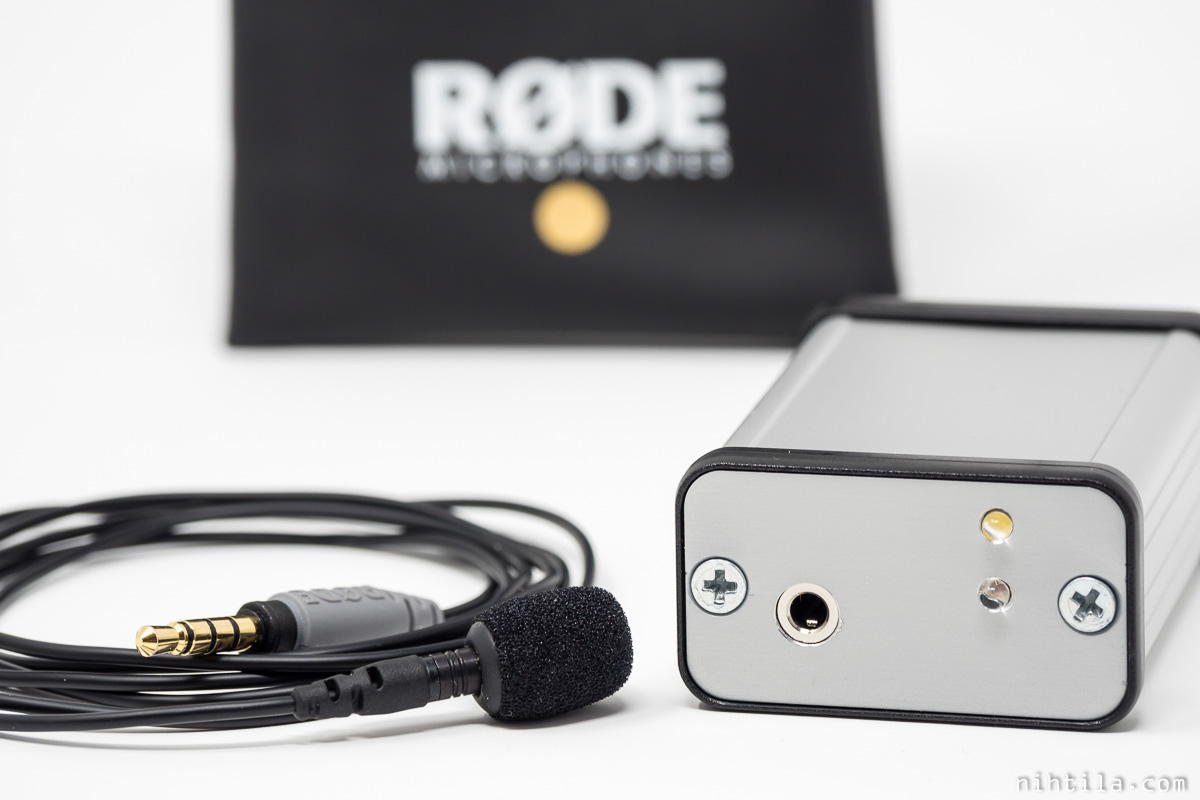
Rode SmartLav+ and USBHI
Therefore, I decided to go for the PCM2912A reference design, only with slight changes. I really wanted this to be an easy-to-use USB-powered plug-and-play device. Just quick schematics, create footprints, straightforward layout, and PCB ready for manufacturing. I think I managed to execute this whole project in around 10 hours (without this post).
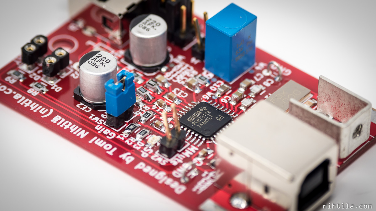
PCM2912A is a USB audio codec with mono microphone input and stereo headphone output
Schematics
Schematic is almost identical to TI PCM2912A reference design. There are elements I don’t like such as electrolytics in audio signal path but they are ok in this application. I have added a dual jumper link selection for OMTP or CTIA type TSSR jack. The difference in these is that mic and GND pins are swapped. Nowadays almost all headsets are CTIA type so default setting should be that.
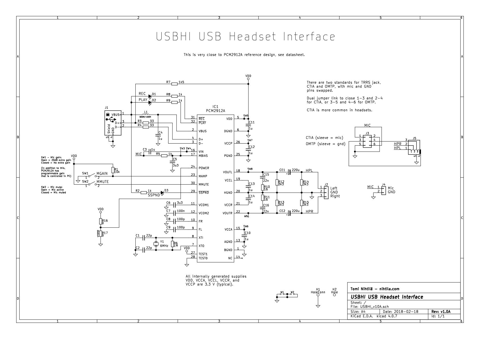
USBHI schematics
All supplies are internally generated by the PCM2912A so only decoupling capacitors are needed for these. It also makes the layout quite straightforward.
Besides CTIA/OMTP selection there are pinheaders for extra mic gain and mic mute. Three LEDs indicate play, record, and USB suspend. Play and record LEDs can be wired on front panel.
Headphone output contains DC level, hence the large electrolytics in the signal path. Condenser microphones typically used in headsets require bias voltage which is fed to the mic module through resistor, and audio then goes through DC-blocking capacitor. This capacitance value is much smaller than in output path so I have used a plastic capacitor.
Power pin of PCM2912A defines whether the device is low-power 100 mA device or higher-power 500 mA device. 100 mA should be plenty for this board but there was slight confusion in the datasheet so I placed resistors R16 and R17 to choose between the modes. Default is logical high for 100 mA mode.
Layout
PCB is very small (for a DIY) partly because I bought a wrong size Hammond enclosure, it was a lot smaller than intended. However, layout is straightforward mostly due to internal supplies – there is not really supply routing. Signal flow is straightforward making layout relatively simple and possible to do it on a small PCB even with two layers. Therefore, I did not want to pay extra for 4-layer PCB. Instead, I chose PCB thickness of only 0.8 mm to bring the ground plane closer.
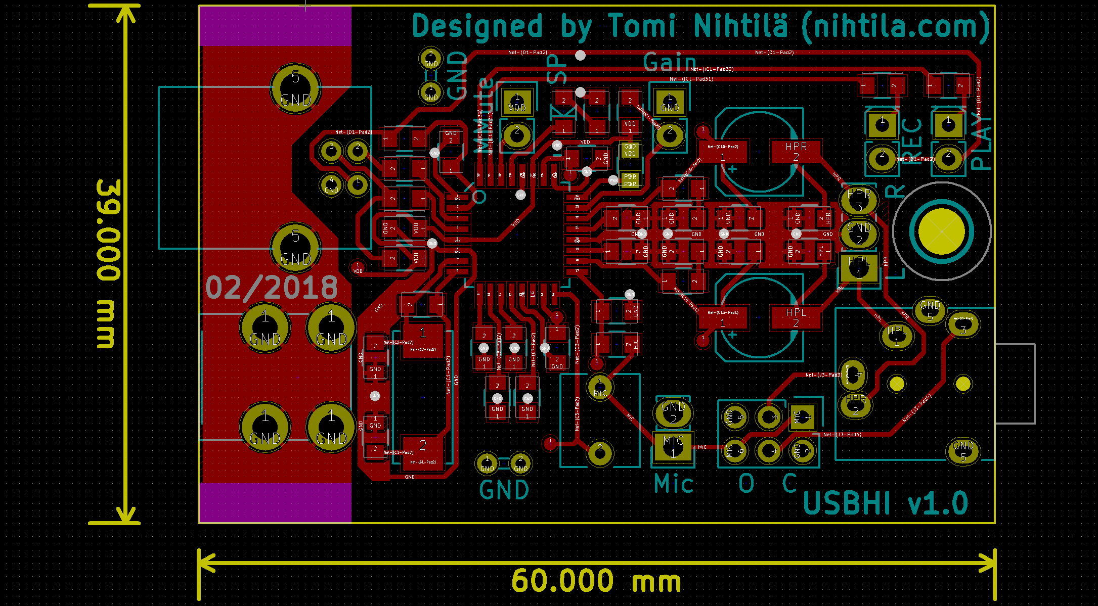
USBHI KiCad layout and PCB dimensions
As usual, schematics and layout have been done with KiCad and PCBs ordered from Elecrow. Components are sourced from Mouser.
Nowadays I want to have reference designators on silkscreen unlike on my older boards, here it was quite tight to fit everything in. Connectors take a lot of space on this small board.
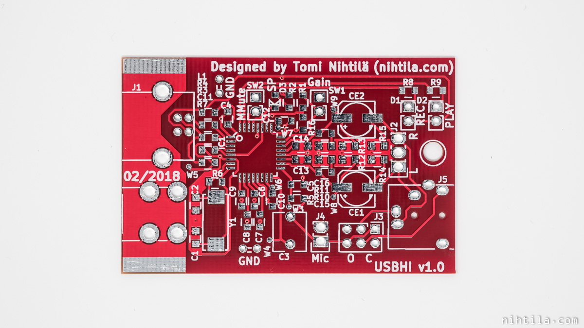
PCB top
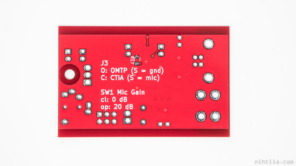
PCB bottom with jumper link instructions
Final design
Before starting layout I chose a small Hammond case for the design. I thought I ordered slightly larger case but this is what I got so I wanted to fit the layout into these dimensions. End result is actually quite cute small box that goes nicely with a small microphone.
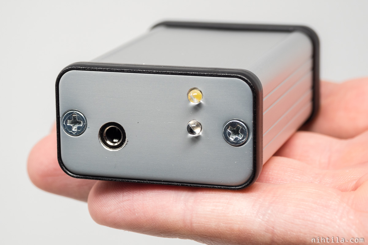
4-pole headset jack and Play and Rec LEDs
Besides headset jack, front panel has Play and Rec LEDs and back panel USB connector and microphone mute switch. As a final thought I must say that PCB screw connector would not have been necessary in this as the PCB and connectors are tight fit in the enclosure. However, in a different enclosure it would be necessary as there is only one mounting hole on the PCB.
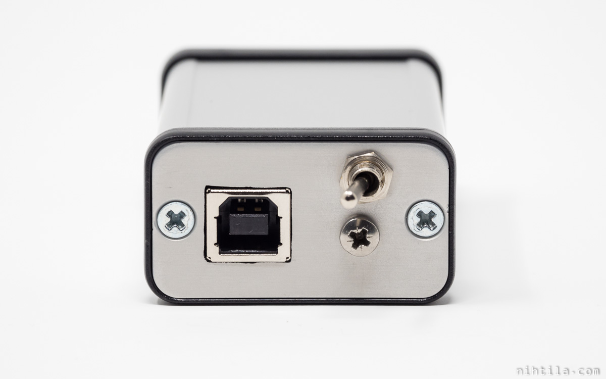
USB connector and microphone mute switch
Important note:
I needed to change the front panel after these photos. As can be seen, sleeve of the TRRS jack is in contact with the case which is grounded. However, this sleeve is microphone in CTIA configuration so it shorts the mic pin to ground! I just made the hole large enough. It is not as pretty but doesn’t look too bad.
Therefore, it is recommended to choose enclosure with plastic end panels. Hammond offers both metal and plastic end panels.
Use on Windows PC
Windows recognises PCM2912A as USB audio codec and uses some standard drivers. No driver installation is required. Codec shows up in both playback and recording device list.
Windows sliders and actual gain and output level
PCM2912A has programmable gain amplifiers (PGA) for input and outputs and these are controlled via USB commands under the hood. I don’t know the details of the implementation but it seems that drivers are using some standard commands and volume slider in Windows actually adjusts the on-chip PGA instead of changing the signal level in Windows. At least the minimum and maximum gains match the datasheet values.
For clarification, by slider here I mean the sliders found in Windows Sound settings, Playback/Recording devices.
Output is relatively clear. Output PGA is adjustable within -76 dB and 0 dB. Therefore, Windows slider at maximum 100 corresponds 0 dBFS signal. I presume slider at 0 is -76 dB but I actually did not measure this. After all, it is practically mute. 0 dBFS level is 0.6*Vcca (Vpp) = 0.7 Vrms.
Microphone input is slightly more confusing. First of all, there is extra 20 dB setting swich which I call external gain here, and in addition to that ADC PGA range is -12…30 dB. When both external gain setting and PGA are at 0 dB, maximum input level is 0.43*Vcca (Vpp) = 0.5 Vrms and this is the situation specifications are given at. The question is how do you know PGA is at 0 dB? You don’t.
The slider also seems to work completely differently on my work Windows 7 laptop and my home Windows 10 desktop. On my work laptop I also used ASIO drivers for measurements so that may be the reason as well. On Win 7 the slider at 0/100 is -12 dB but zero-ish dB is already at 2/100 which is -2 dB, the closest step to zero. Half of the range is used in the first few steps. On my Win 10 PC the slider works a bit better and range is divided more evenly but still you do not know what is the actual gain. This does not really matter in practical microphone use but it makes measurements a bit trickier.
The fact that these sliders are still operational when using ASIO drivers also indicate the signal level is adjusted on-chip and not on Windows.
Measurements
I have measured the board at work using Audio Precision APx555 audio analyser and using ASIO4ALL drivers for USB audio.
SNR is measured using maximum 0 dBFS signal level compared to A-weighted noise and THD+N ratio is measured at -1 dBFS signal. Unless otherwise mentioned, measurement bandwidth is 20 kHz and frequency in single-tone measurements is 997 Hz.
As mentioned above, gain setting in Windows is a bit tricky. ADC gain in these measurements is set to -2 dB which was the closest step to zero. Clipping level is around 650 mVrms, while datasheet states 0 dB level as 0.5 Vrms.
Headphone output is set to 0 dBFS (maximum level) which corresponds 0.7 Vrms.
Key figures
- ADC (microphone input)
- 0 dB external gain
- THD+N ratio: 0.0082 %
- SNR: 90 dB A-w
- 20 dB external gain
- THD+N ratio: 0.015 %
- SNR: 82 dB A-w
- 0 dB external gain
- DAC (headphone output), high-impedance load
- THD+N ratio: 0.011 %
- SNR: 92 dB A-w
- Crosstalk: -86 dB @ 10 kHz
These are on par with the PCM2912A datasheet.
Headphone output (DAC) graphs
Frequency response
Frequency response is a bit bumpier than normally seen. Notice the scaling though – deviations are still only 0.2 dB. The effect seen is a combination of digital interpolation filter ripple and analog filter boost which can be seen on datasheet graphs.
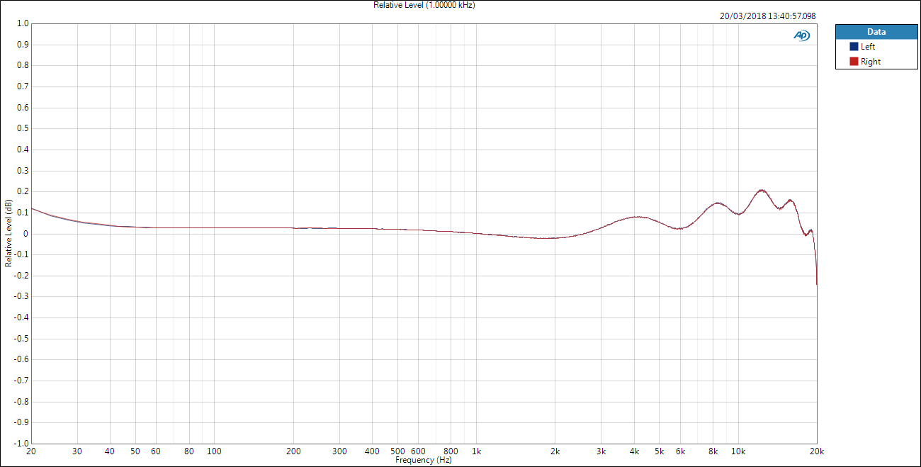
USBHI DAC frequency response
THD+N
Below are graphs of THD+N level and ratio. Specification is 0.01 % typical.
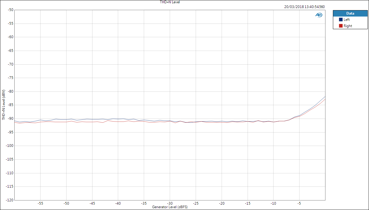
USBHI DAC THD+N level
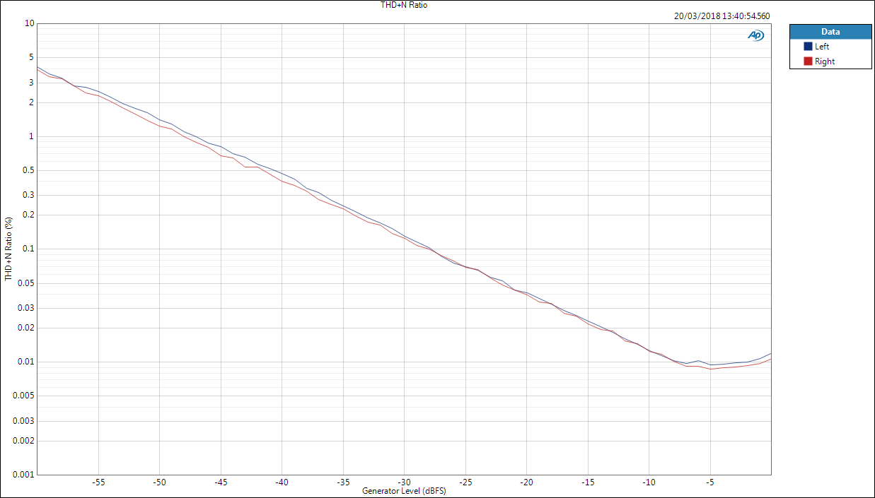
USBHI DAC THD+N ratio
Microphone input (ADC) graphs
Frequency response
Ripple is caused by digital filtering as in DAC. Low-frequency roll-off is due to AC coupling. This depends on the used microphone. Notice scaling again.

USBHI ADC frequency response
THD+N
Below are graphs of THD+N level and ratio. Specification is 0.01 % typical. 0 dBFS level is 650 mV, after that the signal starts clipping.
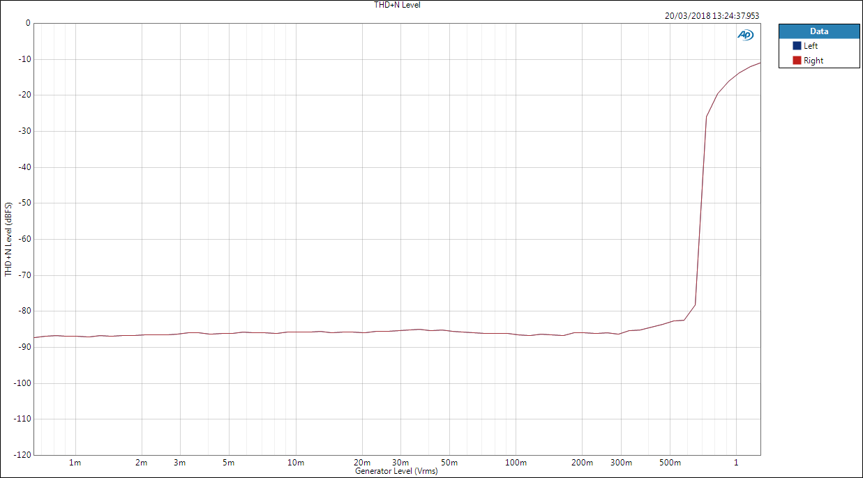
USBHI ADC THD+N level
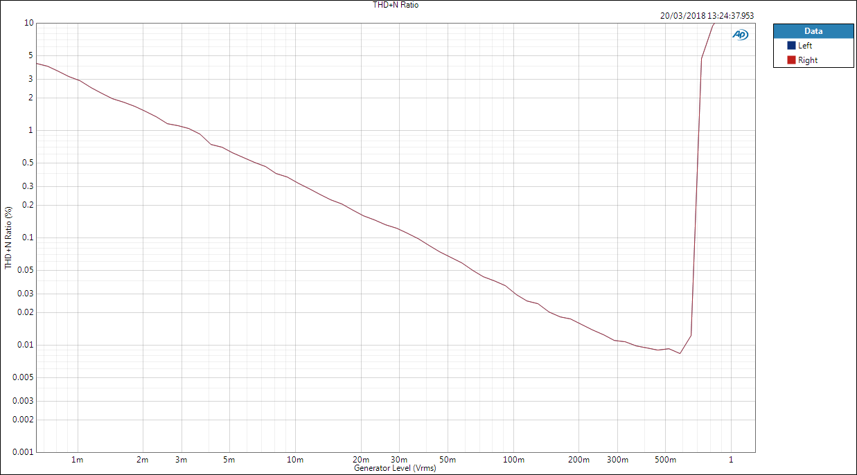
USBHI ADC THD+n ratio
Measurement conclusions
Performance figures meet datasheet specifications. Figures are definitely the weakest in any of my designs yet but that was expected. However, considering the application which is microphone preamplifier for easy voice recording, the numbers are good enough. Moreover, this is a tiny device and very easy to use, just plug in USB cable and microphone. No driver or software installs, no power supplies.
Why didn’t I choose a better USB codec? I don’t think such single-IC solutions exist. Higher quality 24-bit USB audio solutions require dedicated USB-chips followed by audio codecs. All easy to use older codecs like PCM2912A are 16-bit and with more modest specifications.
Files
- v1.0A files
- Schematics
- Component placement top
- Component placement bottom
- BOM
- May not be perfect, check carefully if making order based on BOM
- Prices are in GBP, without VAT, and not up-to-date
References and additional information
Version history
Schematics / PCB version history and known errors and bugs
- v1.0A Initial version
- Play and Rec LEDs could be swapped for easier and more logical front panel orientation
- Not really a PCB issue but care must be taken with TRRS jack; sleeve in CTIA configuration is mic so it must not be in contact with (grounded) enclosure
This page version history
- 26.3.2018 Initial version
5 comments
The screw connector is a nice idea to hold PCB’s in place. Where do you get them from?
I get all my parts from Mouser or Digikey. This one goes with part number ‘534-7790’ on Mouser. It’s not super cheap compared to many other parts but very handy in some cases.
Bummer, Farnell does not seem to have them :/ oh well .
Thank you for telling me though
Finally today I got my PCB for my PCM2912A DAC I’m building…only to have (i think?) a solder bridge on the DAC and burn the only chip I have… 🙁
I also built a PCM2912A based soundcard and always get that click/pop when the output cap charges or discharges (I guess the same is for your design). Do you have an idea how to suppress it?
I lowered the output resistor to 68 Ohm which makes it a bit less loud already, but there has to be a better solution. I thought of an analog switch like the TS5A22362 (just the first promising hit) at the output, controlled by the play indicator, but maybe there’s a better solution avoiding a PCB redesign.
(My design is on gitlab for the case somebody is interested in it)