
Progress has been slow due to other things in life but last few weeks have been busy on finalising everything. More measurements have been done and PCBs are finalised. First batch of boards is in production and should be available in September.
Current status
The downside of doing these projects in free time is that sometimes things lag behind due to other commitments. Actual 9-to-5 job, holidays, other life events, or just frustration and being fed up spending a lot of free time on electronics which happens to be similar to the actual job. And then of course the fact that projects always take more time to finish than anticipated. A lot more, especially when the bar is a bit higher.
Anyway, overall I really enjoy doing this and we have reached the point that PCB assembly order is placed and I have (re-)designed additional boards to make the whole system usable. This is a modular system with following boards:
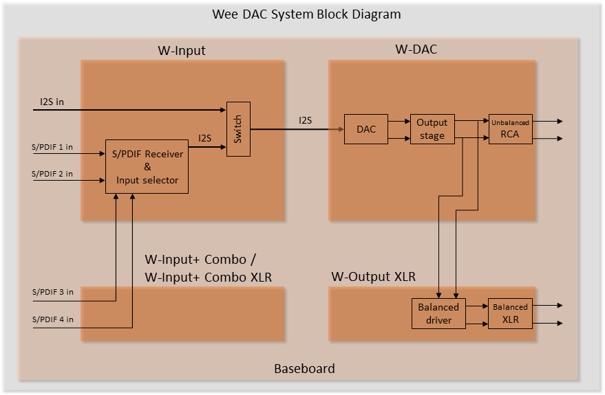
- W-Input
- Input board with Coaxial and Toslink S/PDIF inputs and I2S input
- More S/PDIF inputs can be added with Input addon boards (also balanced AES/EBU)
- W-DAC
- DAC board with AK4490 or AK4493 DAC and unbalanced RCA outputs
- Balanced output can be added with W-Output XLR
- Detailed performance measurements will be available
- Selection of baseboards supporting
- A vertical stack of W-Input and W-DAC (plus additionally W-Output XLR)
- A horizontal stack of W-Input and W-DAC (plus additionally W-Output XLR and Input addons)
- Baseboards contain pre-regulators or are breakout boards for external supplies
Depending on the form factor requirements, suitable baseboard can be chosen for either vertical or horizontal stack. Not all optional boards can be used in both options. It’s also possible to use W-DAC only for external I2S. More details will follow soon in another post regarding system level description.
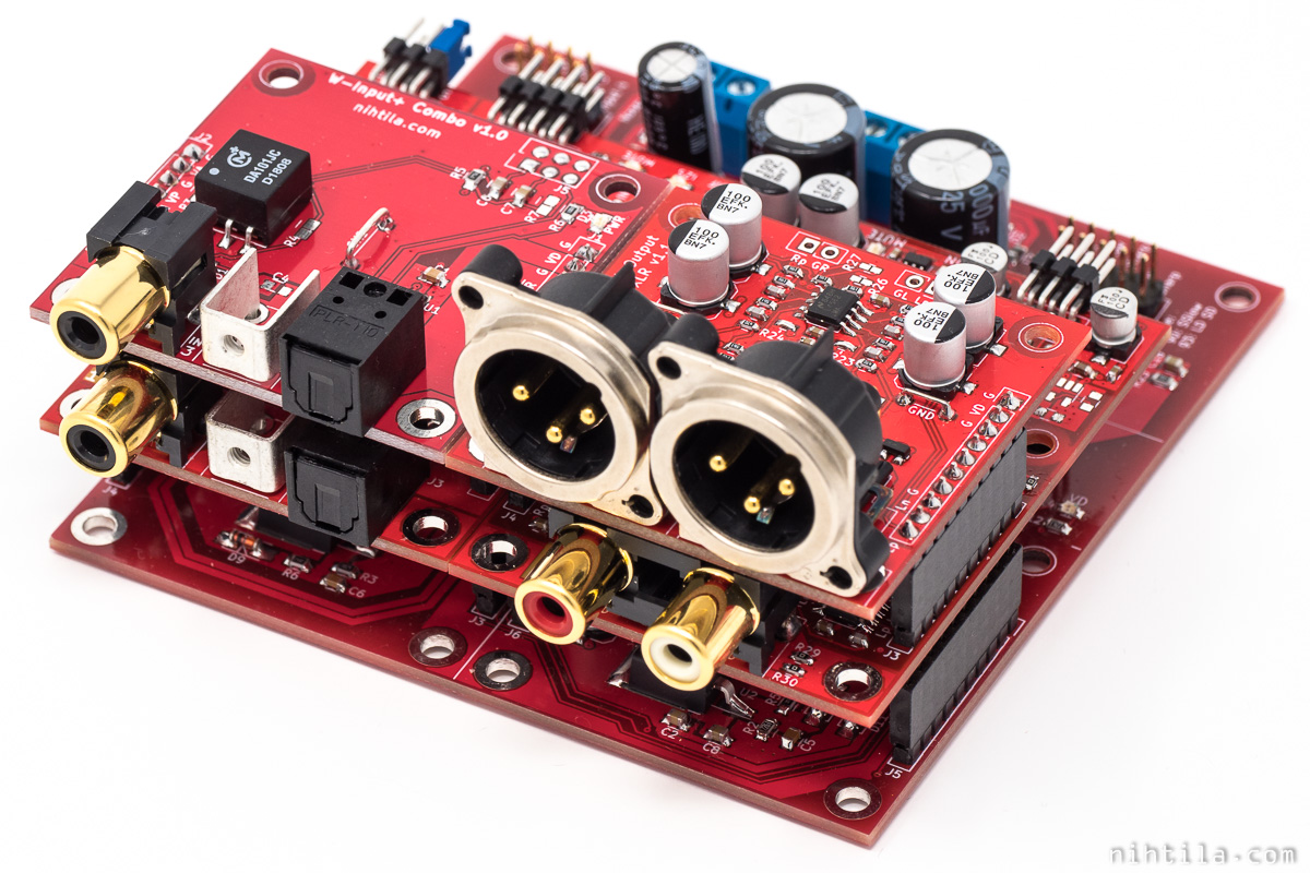
Horizontal stack with extra input and output boards.
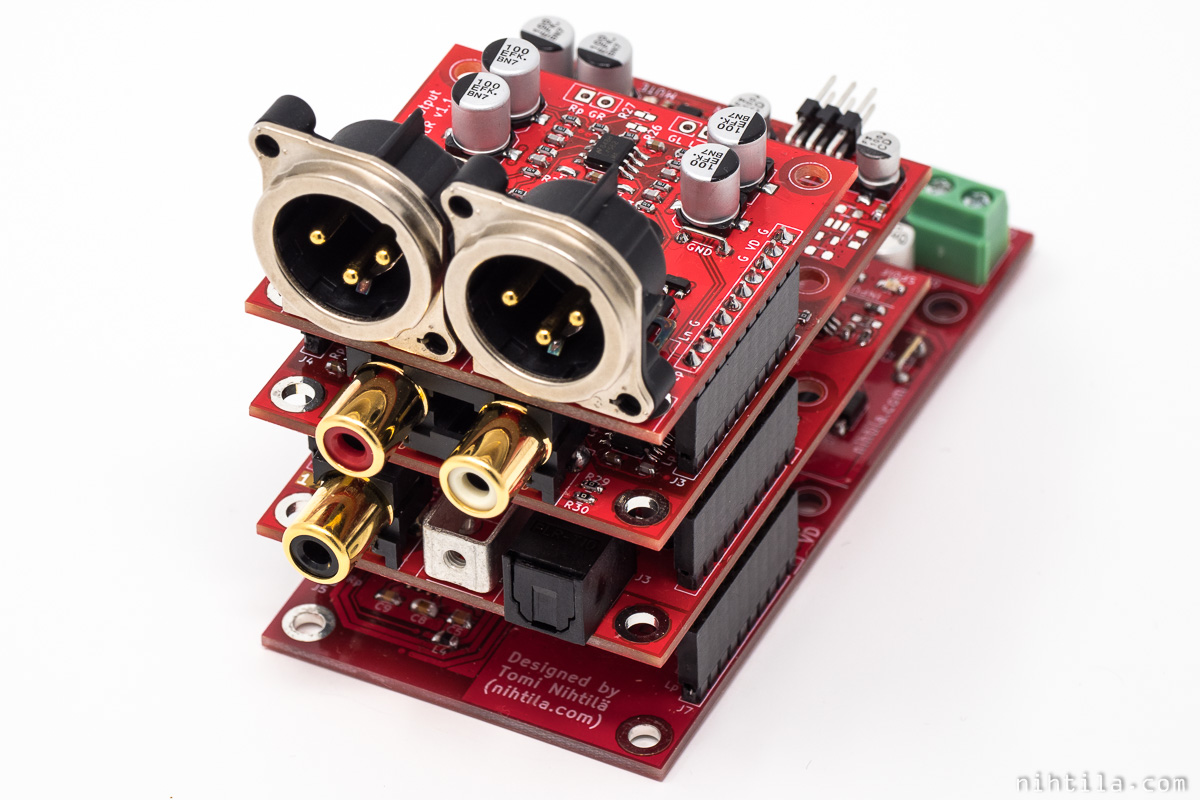
Vertical stack with XLR output addon.
Following block diagram illustrates division between boards.
PCB assembly
I have placed an order for partial builds of W-Input, W-DAC, and W-Output XLR. They will not be fully populated but time-consuming passives and some ICs will be populated by an assembly house. There are few reasons why I didn’t order full builds.
First of all, different board versions. For example, I didn’t want to populate the DAC chip as some boards will have AK4490 and some AK4493. There are still a few components that I have not decided exactly what to put. I will populate and measure few different boards of the same version to get more statistically solid measurement data.
Secondly, as important, is money. This is still all hobby and everything so far I have funded from my own pocket and have not made a dime along the way. Doing even a small batch with some slightly pricier ICs will cost thousands of dollars. And it’s difficult to forecast how many boards you expect to sell. Therefore, by leaving the expensive ICs and connectors out of the build, the one-off assembly payment becomes significantly smaller. I can then order the rest of the components in smaller quantities when I start finalising and selling the boards.
By default, I will sell the boards without connectors soldered. This way the end user can decide to use on-board connectors or wire them off-board.
Baseboards will not be factory-assembled now as I am only waiting for the prototype PCBs to test, arriving in next few days. I will then hand-assemble a small amount to start with and consider PCBA later on.
Board availability
I expect to start selling the boards in September. I should get the partial builds in late August or early September. I will first offer them here on my website and may consider an online marketplace later on.
Check out the website in late August to early September, and sign up to the mailing list, there may be slightly lower early bird rates available.
Pricing
Unfortunately I do not want to fix the prices yet. I have done my math but as I am not absolutely sure about all costs involved yet, I cannot commit on exact prices. To give some indication, expect W-DAC to be around 100 USD and the rest less than that. I will try to offer some kind of bundle with W-Input and a simple baseboard for 200 USD.
Major changes along the way
Let’s look back a bit. I started working on these boards somewhere in Autumn 2018.
I started with a baseboard with voltage regulators, and W-Input and W-DAC were using these supplies directly. This turned out to be a bad decision. These high performance DACs really need local on-board regulators. Therefore, after measurements on a test board this significant system change was done. Also some voltages were changed. All boards now take in:
- +-15V for opamps (no on-board LDOs for these)
- 5V for digital (3.3V on-board regulators)
- 7.2V (5V and 3.3V on-board regulators, and in some cases also higher voltage could be used)
The last 7.2VA supply is somewhat redundant as also +15V could be used in most cases but I left it in place as it may be useful in some scenarios.
First round of Wee DAC boards at the end of 2018.
Board interface needed to be changed at this point as well. Simple keying was included by changing two 1×10 pinheaders to 1×10 + 1×8 pinheaders.
In order to incorporate these major changes in supplies the boards were made larger from 50mm x 50mm to 70mm x 50mm. There are also more extra capacitor placeholders now.
AK4493 support was added on W-DAC PCB.
Reset and mute circuits were changed. These are mostly responsible for good pop and click operation.
W-Input supports extra inputs with W-Input Addon boards. Also I2S input was added on W-Input. This can be used for external USB to I2S modules.
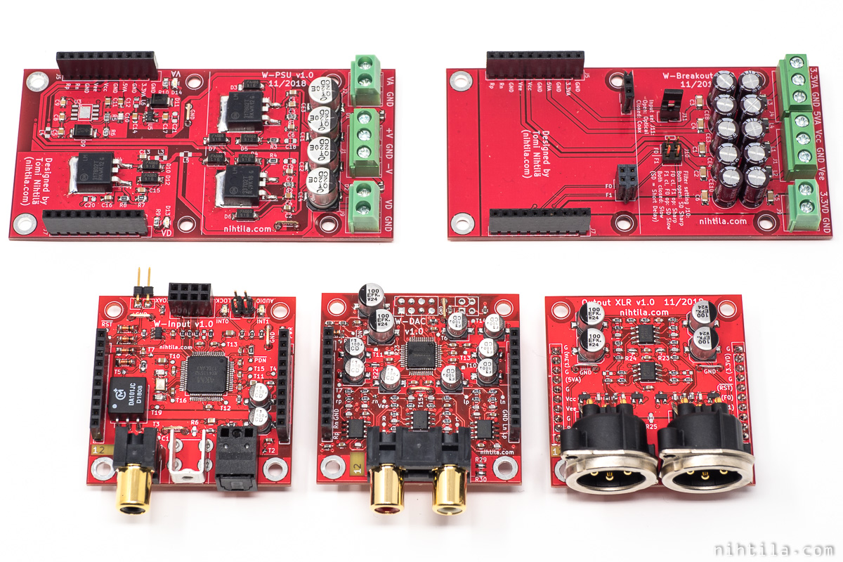
Comprehensive range of baseboards was developed. These support vertical or horizontal stacks, and come with pre-regulators or breakout only.
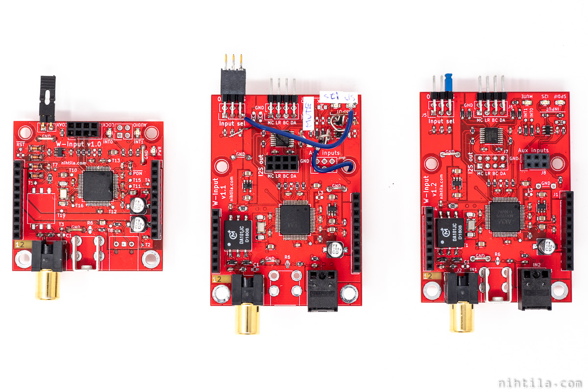
W-Input evolution.
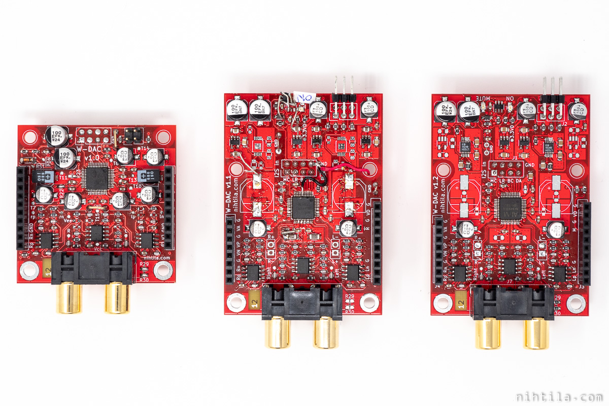
W-DAC evolution.
DAC comparison
I have measured the boards with AK4490 and AK4493 which are almost pin-compatible; the PCB supports both. When used with the best regulators, measurement results are very close to one another. And it’s not really a surprise as so are their specs. However, AK4493 is slightly better; and it’s also more expensive.
These are not guaranteed performance figures for W-DAC but what I have seen on bemch when using the best regulators:
- AK4490: Dynamic range 119dBA, THD+N at 1kHz 0dBFS: -113dB
- AK4493: Dynamic range 121dBA, THD+N at 1kHz 0dBFS: -115dB
It’s worth mentioning here that these figures are better than typical specification of these ICs. Typical THD+N spec for AK4490 is -112dB and max spec -105dB. Therefore, I’d say measuring -113dB relatively consistently is almost surprising. However, this means that another batch of ICs may show completely different performance and still be within spec. Therefore, I will need to place in my disclaimer that this kind of performance is not guaranteed. Most likely there will not be large difference though. Hopefully.
It’s also interesting to see how close to these test figures I will get with the production batch. Keeping quality high and consistent when outsourcing is an exercise of its own and something new to me.

Either AK4490 or AK4493 can be used on the same PCB.
W-DAC voltage regulators
There were tests carried out with multiple regulators from which two stood out.
LT3042
Analog (Linear) LT3042 has been the king of the castle all the time. Solid superior performance. However, I have seen quite high sensitivity to small changes that can swing the performance figures. It may be just because we are at so low figures here.
After all, it’s about consistency within the chosen solution so in order to test repeatability, I populated few boards to measure. The results were quite consistent although one board showed too high delta. To really test this, I will carry out final measurements after the assembled boards arrive.
By the way, this is one of the best voltage regulators out there. Ever. It has stunning noise and PSRR performance. It also means it’s not cheap.
LP2992
TI LP2992 is still a good alternative as it provides very good results for a fraction of the price of LT3042. However, I was not able to flatten the THD+N vs frequency curve so low-frequency distortion is still significantly higher.
LDO conclusions
I will make the final decision after carrying out tests on larger number of boards after the assembled ones arrive but for now I feel that I will use LT3042 for both AK4490 and AK4493 versions.

Either LP2992 or LT3042 can be used on the same PCB.
W-DAC capacitor tests
Besides voltage regulators, capacitors have been one major focus on W-DAC measurements. Along with regulators, decoupling caps are very important determining the system performance. There has been loads of tests done and it’s impossible to cover everything but here are some examples.
As a conclusion it can be said that some very small changes in schematic or layout may have significant impact on performance figures. Therefore, measurements are really the only way to see how things work. And in order to really conclude how solid a solution is, the measurements should be done on more than one board.
LDO and electrolytics
In the new PCB revision there are placeholders for large 10mm electrolytics next to VREF pins. In many tests THD+N really improves by adding as much capacitance as possible on VREF. However, again this depends on the LDO used. For example LT3042 does not like excess capacitance at its output, which is also stated in the datasheet. Too much capacitance can lead to performance degradation.
I have been doing tests with various polyelectrolytic capacitors as well as bulk electrolytics. If the circuit really likes excess capacitance, such as LP2992 circuit, the more the merrier. There may be slight improvement in some cases if using poly electrolytic instead of bulk keeping the capacitance equal.
Ceramics
There are several ceramic capacitor placeholders in the secondary side of the LDOs. First one is straight at the LDO output which is necessary for its stability. Then there are small caps directly at VREF and VDD pins plus some additional placeholders slightly farther away.
This proved to be quite an exercise trying to draw conclusions. In some cases extra large ceramics at VDD made a big improvement on the performance, in some cases degradation, depending on the LDO and other capacitors in place.
The same goes for extra VREF capacitance, and even slightly changing the location of a capacitor already made a difference in some cases.
Capacitor sensitivity
All this capacitor sensitivity made it tricky to draw conclusion what is good and what is bad. It sounds like something is in the borderline of stability or so and even tiny differences cause significant impact in measured figures. However, when a solution was found it seemed relatively consistent across boards. While there are still correlation to be done on larger number of boards, it looks like the results are quite consistent.

There are several capacitor placeholders in the DAC IC surroundings.
Pop and click performance
Pop and click mean unwanted glitches when turning power on or off, or switching input.
There is a major difference between AK4490 and AK4493 in terms of pop and click behaviour. When AK4490 comes out of reset, it produces a loud near full-scale pop, while AK4493 does not. These ICs not only go on reset state when power down pin is pulled low but also when clocks are not present.
This AK4490 pop could be just a startup pop which is somewhat acceptable. However, having I2S input in the system adds some concerns.
If I2S input is selected but nothing is connected there, DAC loses clocks and goes to reset. Then, when changing back to any of the S/PDIF inputs, clocks become active and DAC comes out of reset – with a pop when using AK4490. This does not happen when switching between S/PDIF inputs as S/PDIF receiver on W-Input always drives clock signals.
Therefore, user must be careful with I2S input. If not used, don’t make it selectable at all. If it is used, try to ensure there are always clocks present; e.g. the external I2S module always drives some clocks.
Or just use AK4493 that does not have the issue.
DAC with output circuit without external mute will always generate some unwanted pops. It is always end user’s responsibility to protect their speakers, headphones, and ears from potentially harmful pops and clicks. Power amplifier or headphone amplifier should always have a mute circuit included. A circuit that delays power-on but is instant at power-off is typically enough even when turning the whole system on/off simultaneously. This is how I have done it; I just have one master switch for the extension cord that powers my system with headphone amplifier, power amplifier, and active speakers and there are no pops at all.
W-Input tests
W-Input has been working pretty much since the beginning. There has been major changes due to system level changes, such as adding on-board regulators and changing interface. Otherwise the biggest addition was I2S input when the boards were made bigger.
The best evaluation for W-Input is to compare W-DAC performance when fed directly with I2S or with S/PDIF via W-Input. As the performance is identical, we can conclude that W-Input works as it should and is not a bottleneck in the system.
Conclusions
A lot has changed along the way, and I have learned a ton of new things! And that’s one reason I am doing this. I have spent a lot of time and money on this project and while it is partly learning money, I hope I could get some of it back. So if you are interested in these boards, please watch this space. In the next couple of weeks there will be an opportunity to buy boards.
If you are interested, you can already sign up for my brand new newsletter.
5 comments
Nice to see that it goes forward again. Unfortunately, these stacked boards are very high. Everything on a single board would have been better for my needs. Nevertheless, it is an exceptional project.
True, it becomes high. The narrow and high is maybe not very practical. I’d assume using the wider option when S/PDIF inputs are needed, and the narrow one for multichannel I2S without W-Input.
This is one approach and won’t suit all needs, I agree with that. My next DAC concept may be something else, for example all in one board. It’s handy to stack at least connectors somehow though as otherwise the PCB becomes very long (and expensive). Especially XLRs take a lot of space.
I think one good way to get publicity is to send one sample to Amirm at AudioScienceReview.com for review and measurements. A lot of people who value objective performance follow that forum. A working stack should be fine, no case necessarily needed.
AudioScienceReview.com , one of my favorite sites! This man owns an AP555. Very nice tests!
Yeah, I hope I do one day as well 🙂 Lucky already having APx555 to use at work but debugging and experimenting would be so much easier at home. But 555 is state of the art kit and priced accordingly – you can buy a good car for that price. Not exactly a hobbyist’s piece of kit.